
Filleting Knife Blade

a technology of a knife blade and a blade is applied in the field of knife blade construction, which can solve the problems of difficult lengthwise piercing of heavily scaled areas, difficult peeling, and limitations of the long filleting blad

Inactive Publication Date: 2015-10-01
SCOBIE MICHAEL A N
View PDF1 Cites 1 Cited by
  • Summary
  • Abstract
  • Description
  • Claims
  • Application Information

AI Technical Summary

Benefits of technology

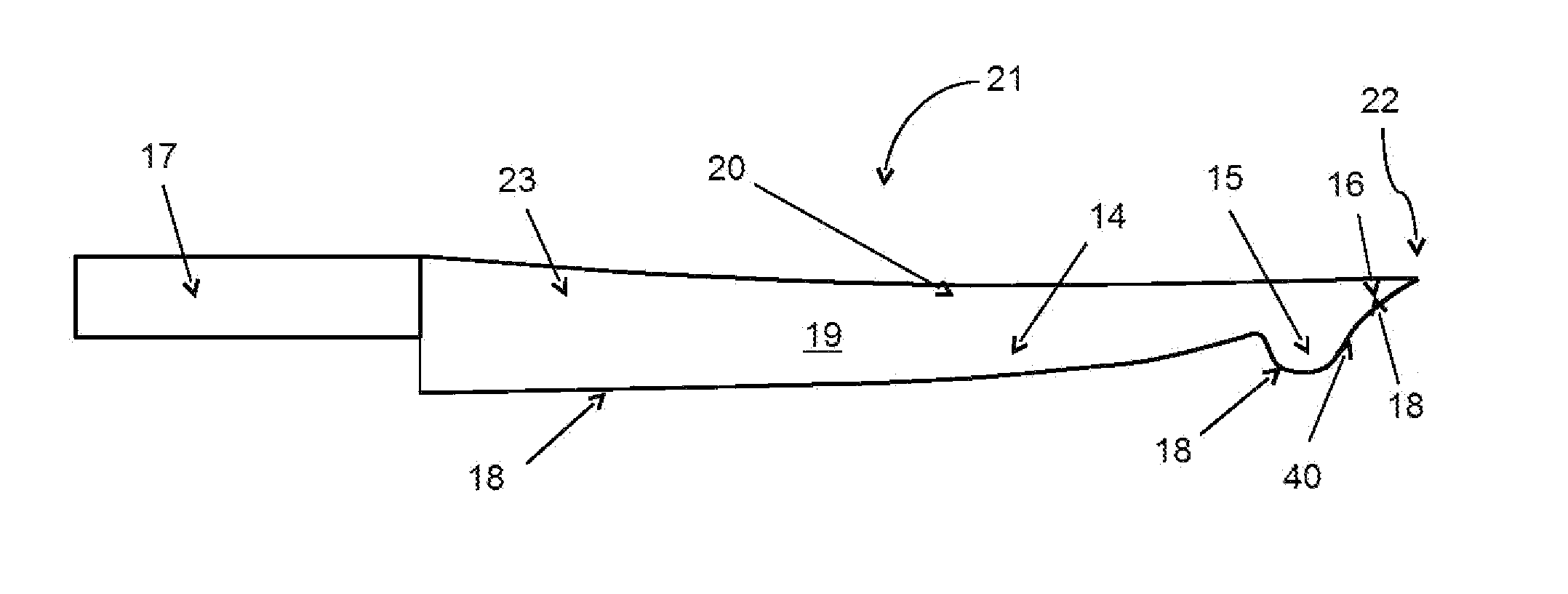
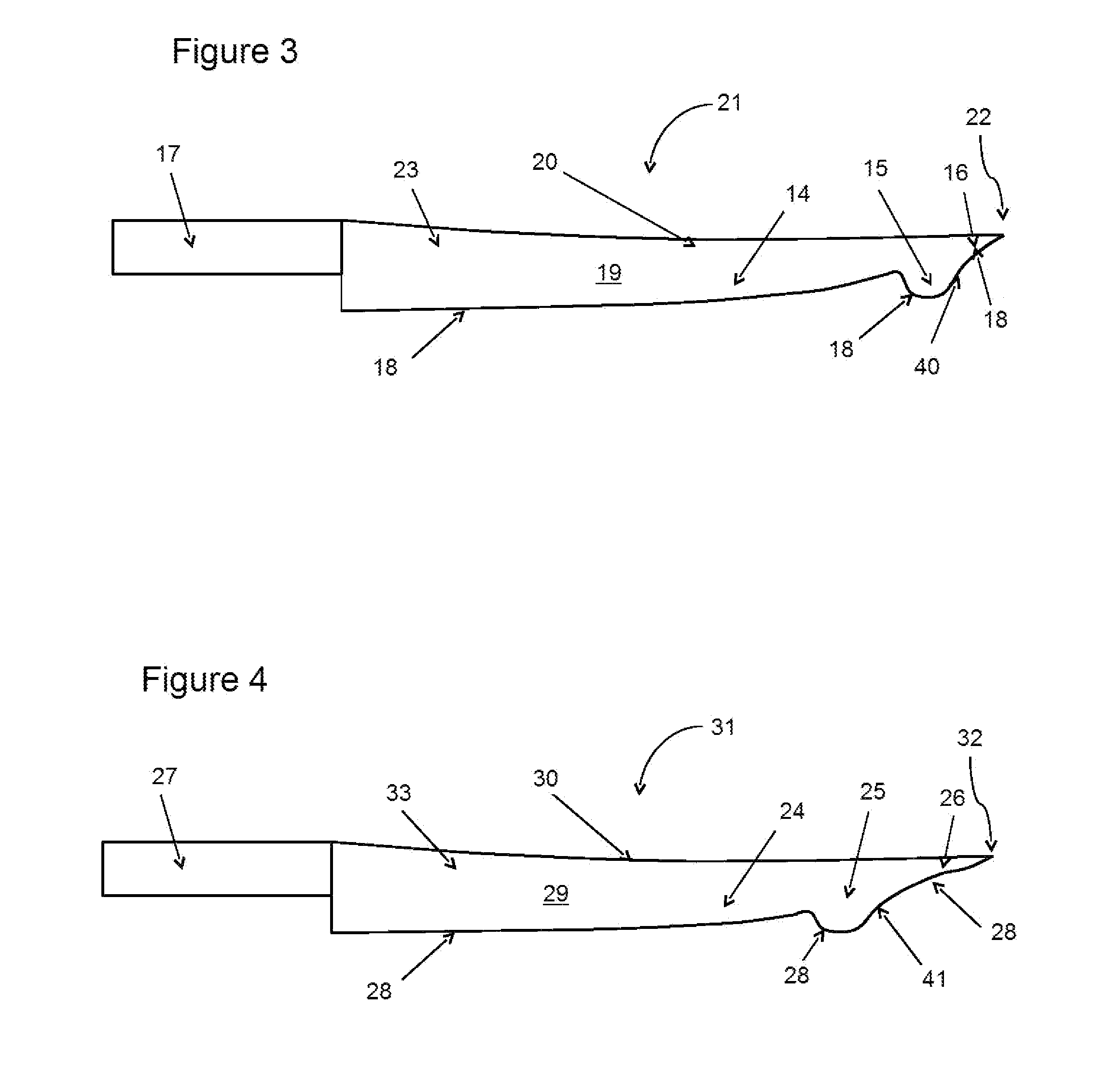
The present invention provides a filleting knife with characteristics of both long blade and "ulo"-like blade types. The blade has a sharp edge and side surfaces, with a protrusion that extends outwards from the edge to form an "ulo"-like protrusion. This arrangement allows for better filleting performance and makes the knife easier to use. The handle section typically has a long blade section adjacent to it. The technical effects of the invention are improved filleting performance and ease of use.

Problems solved by technology

Secondly, the length of blade allows thick portions of the flesh to be skewered before any sideways cutting motion takes place.
Thirdly, due to the flexible nature of the blade, the flesh can be peeled away from the skin once the fillet has been separated from the fish.
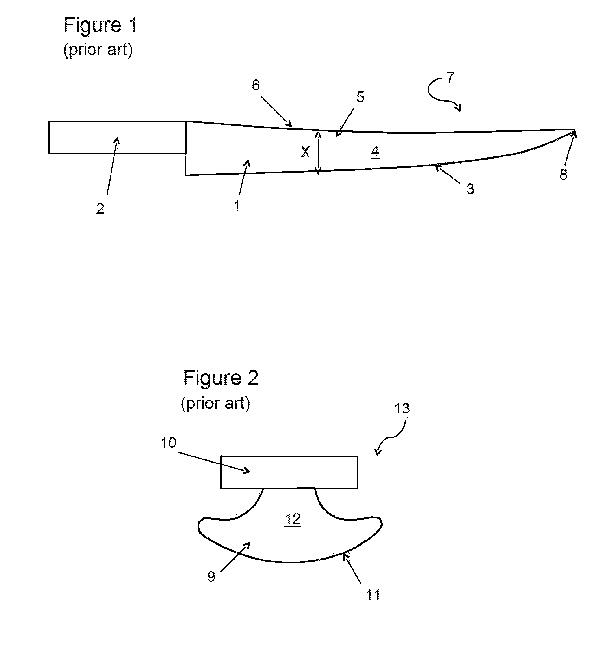
Conversely, there are limitations associated with the long filleting blade.
Firstly, due to the relatively straight nature of the blade, pressure points cannot be created along the blade's length which can make lengthwise piercing of heavily scaled areas difficult.
Secondly, when the blade tip is buried within the flesh, cutting motion can only effectively occur in one direction, towards the handle.
Cutting motion away from the handle can frequently result in the blade tip getting caught or piercing of internal organs.
Conversely, there are limitations associated with the “ulu”-like filleting blade.
Due to its compactness and handle position, it is not possible to skewer or achieve single, deep penetrations of the flesh.
Secondly, due to its bulky nature, precision movements required to separate flesh from bony structures such as the ribcage and spine, are difficult.
However, the limitation of this blade is that the cutting surface is only at the end of the scalpel, and therefore it is also difficult to skewer or achieve single, deep penetrations of the flesh.

Method used


Image

  • Filleting Knife Blade
  • Filleting Knife Blade
  • Filleting Knife Blade

Examples


second embodiment

[0036]FIG. 4 is a side view of the present invention.

DETAILED DESCRIPTION OF THE PREFERRED EMBODIMENTS

[0037]The novel features which are believed to be characteristic of the present invention, as to its structure, organization, use and method of operation, together with further objectives and advantages thereof, will be better understood from the following drawings in which a presently preferred embodiment of the invention will now be illustrated by way of example only. In the drawings, like reference numerals depict like elements.

[0038]It is expressly understood, however, that the drawings are for the purpose of illustration and description only and are not intended as a definition of the limits of the invention. Also, unless otherwise specifically noted, all of the features described herein may be combined with any of the above aspects, in any combination.

[0039]The present invention utilizes the combination of long blade and “ulu”-like blade characteristics into one filleting blad...


PUM


Abstract

A filleting knife blade is provided having a blade section, which includes an “ulu”-like flare or protrusion. The “ulu”-like protrusion offers a region of increased cutting pressure which is especially effective for cutting through fish skin and scales. Also, the curved shape of the “ulu”-like protrusion on the blade allows slicing of interior flesh in both directions parallel to the blade without fear of piercing internal organs or catching the blade tip. This is effective for peeling flesh way from bony structures such as the rib cage or spine, and is especially effective for filleting fish species such as bass or ling which have pronounced ribcage structures.

Description

FIELD OF THE INVENTION[0001]The present invention relates to the field of knives, and in particular to a filleting knife blade construction.BACKGROUND OF THE INVENTION[0002]A number of previous inventions have been developed and / or patented pertaining to knife blades designed specifically for filleting of fish. Also, various knife designs are commercially available today that are meant to perform this task. In general, there are two distinct knife blade types used for this purpose.[0003]The first type is the long, thin filleting blade. Although the commercially available long blade filleting knives vary in style details, their general design features and functionality remain similar in nature.[0004]For example, U.S. Pat. No. 4,825,552 (Bendickson, 1989) discloses a “fillet knife having a flexible handle”. Although this patent focuses only on an improved, more flexible handle, it does demonstrate the general design nature of the prior art; which is a long, thin and flexible blade nar...

Claims


Application Information

Patent Timeline
IPC IPC(8): B26B9/02A22C25/00B26B3/00A22C25/16
CPCB26B9/02B26B3/00A22C25/006A22C25/16B26B9/00A22C25/185
Inventor SCOBIE, MICHAEL A.N.
Owner SCOBIE MICHAEL A N
Learn More