Machine tool
a tool and tool mount technology, applied in the field of machine tools, can solve the problems of difficult replacement operation of the tool mount, large machine in the up and down direction, and large size of the machine in the up and down direction, and achieve the effect of improving the quality of the tool moun
- Summary
- Abstract
- Description
- Claims
- Application Information
AI Technical Summary
Benefits of technology
Problems solved by technology
Method used
Image
Examples
embodiment 1
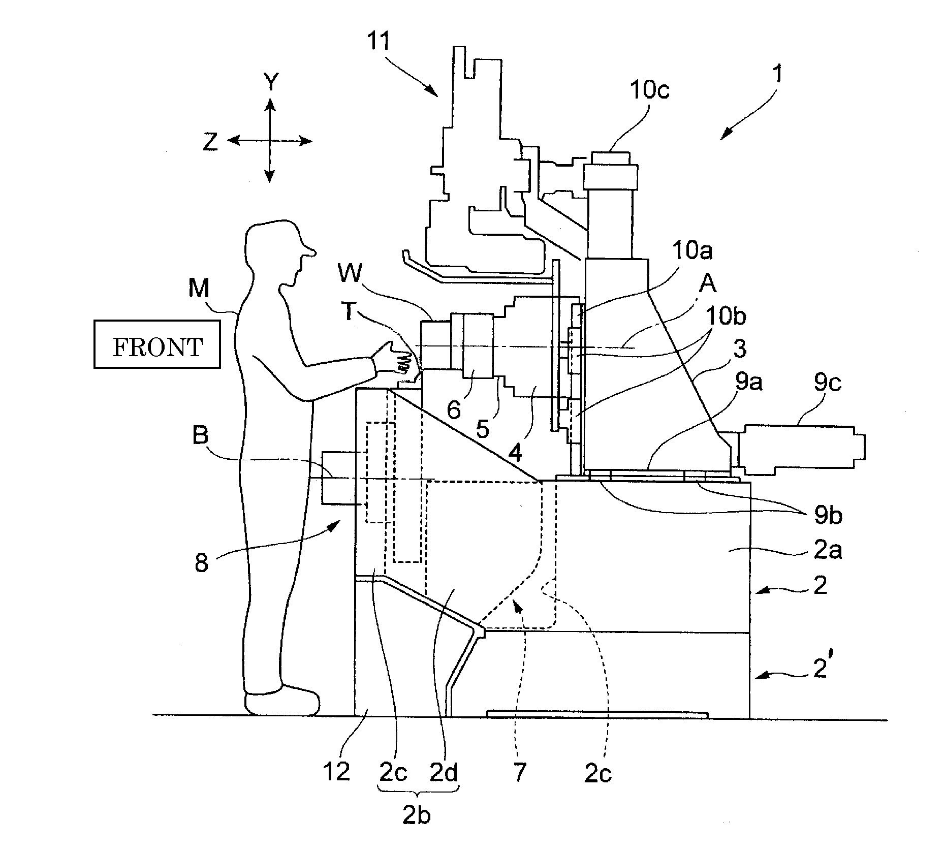
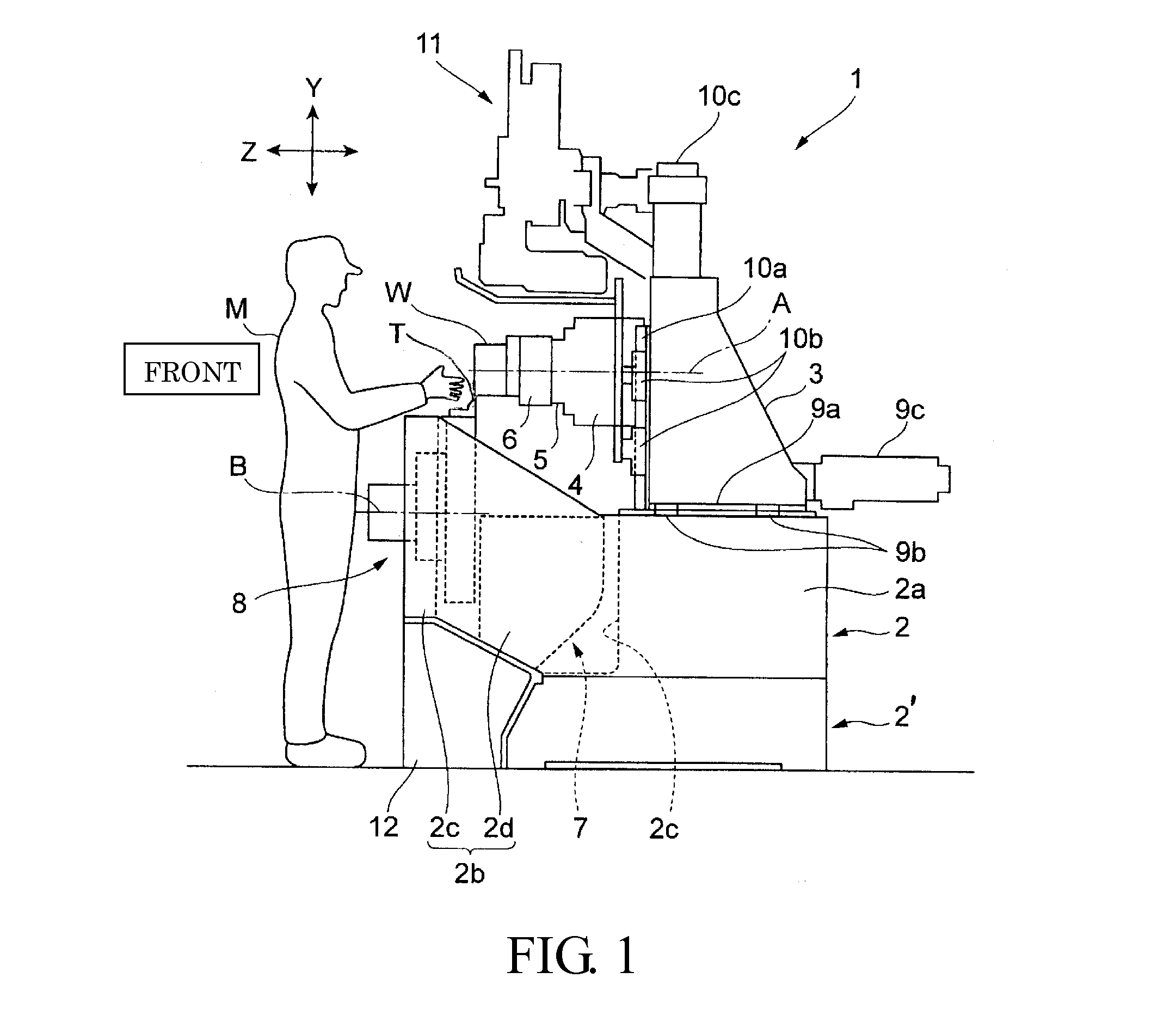
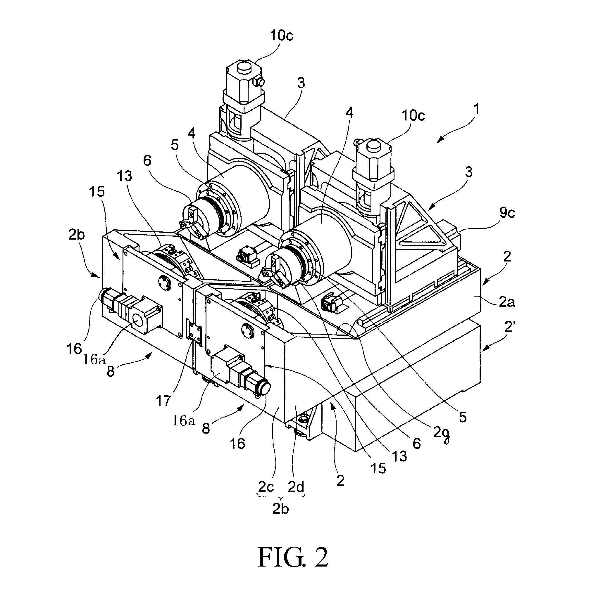
[0033]FIGS. 1 to 4 are drawings for explaining a lathe according to Embodiment 1 of the present invention. Further, in this embodiment, “front and back” respectively refers to a closer side and a farther side when seen from an operator M positioned at the front side of the machine, and “left and right” respectively refer to the left and the right side when seen from the operator M.
[0034]In the drawing, the reference symbol “1” is a type of lathe having spindles facing the operator M side. As best shown in FIG. 2, the lathe 1 is equipped with a pair of left and right beds 2 and 2, columns 3 and 3 arranged on base sections 2a and 2a of the beds 2 and 2 movably in the front and back direction (Z-axis direction as indicated in FIG. 1), spindle heads 4 and 4 movably supported on the front face of each column 3 in the up and down direction (Y-axis direction as indicated in FIG. 1), and tool mounts 8 and 8 arranged on the operator M side. The pair of beds 2 and 2 is mounted on a common bed...
embodiment 2
[0055]FIGS. 6 to 8 are drawings for explaining a lathe according to Embodiment 2 of the present invention. In the drawing, the same symbol as that in FIGS. 1 to 4 denotes the same or corresponding part.
[0056]In Embodiment 2, an indexing motor 26 is arranged below a chip accommodation section 27. The chip accommodation section 27 has a rectangular shape in a planar view surrounded by a bottom wall 27a, a rear side vertical wall 27b, vertical walls 27c and 27c on left and right sides, and a supporting plate 15, and is formed to extend from the below of the spindle 5 to the below of the turret 13.
[0057]The indexing motor 26 is set so that the main body section 26a is accommodated inside the motor accommodation section 2d formed below the bottom wall 27a of the chip accommodation section 27. Further, the flange part 26b is fastened and fixed by bolts to the attachment wall 2e of the motor accommodation section 2d.
[0058]A drive pulley 26d having meshing teeth is fixed to an output shaft...
PUM
| Property | Measurement | Unit |
|---|---|---|
| dimensions | aaaaa | aaaaa |
| dimension | aaaaa | aaaaa |
| stiffness | aaaaa | aaaaa |
Abstract
Description
Claims
Application Information
 - R&D
- Intellectual Property
- Life Sciences
- Materials
- Tech Scout
- Unparalleled Data Quality
- Higher Quality Content
- 60% Fewer Hallucinations
Browse by: Latest US Patents, China's latest patents, Technical Efficacy Thesaurus, Application Domain, Technology Topic, Popular Technical Reports.
© 2025 PatSnap. All rights reserved.Legal|Privacy policy|Modern Slavery Act Transparency Statement|Sitemap|About US| Contact US: help@patsnap.com


