
Power socket temperature alarm device

a technology of temperature alarm and power socket, which is applied in the direction of fire alarm, coupling device connection, instruments, etc., can solve the problems of unplanned damage, serious problem, and temperature rise of operation, and achieve the effect of sufficient tim

Inactive Publication Date: 2015-09-17
YANG WEI LI
View PDF31 Cites 11 Cited by
  • Summary
  • Abstract
  • Description
  • Claims
  • Application Information

AI Technical Summary

Benefits of technology

The present invention provides a power socket module with multiple temperature detection elements to individually monitor the operating temperature. When the temperature reaches a certain level, the output of the detection elements is changed to activate a processing circuit module. The processing circuit module then sends out a lighting alarm and a sounding alarm to notify the user of the hazard situation and give them enough time to handle it. This arrangement ensures that the electrical power supplied through the extension power cord is not abruptly cut off and achieves a safer and practical advantage of multiple stages of safety alarming.

Problems solved by technology

When a problem occurs in the use or operation thereof, such as overloading or a poor contact, rise of operation temperature will definitely result.
However, this often causes a serious problem.
When power is cut off instantaneously, all the electrical devices that are connected to the circuit receiving the power supply will be forced to stop operation, leading to unexpected damage, such as unsaved computer data or interruption of operations that cannot be interrupted.
The current practice for handling this problem by simply cutting off the power supply may not be a perfect strategy.

Method used


Image

  • Power socket temperature alarm device
  • Power socket temperature alarm device
  • Power socket temperature alarm device

Examples


Embodiment Construction

[0016]The following descriptions are exemplary embodiments only, and are not intended to limit the scope, applicability or configuration of the invention in any way. Rather, the following description provides a convenient illustration for implementing exemplary embodiments of the invention. Various changes to the described embodiments may be made in the function and arrangement of the elements described without departing from the scope of the invention as set forth in the appended claims.

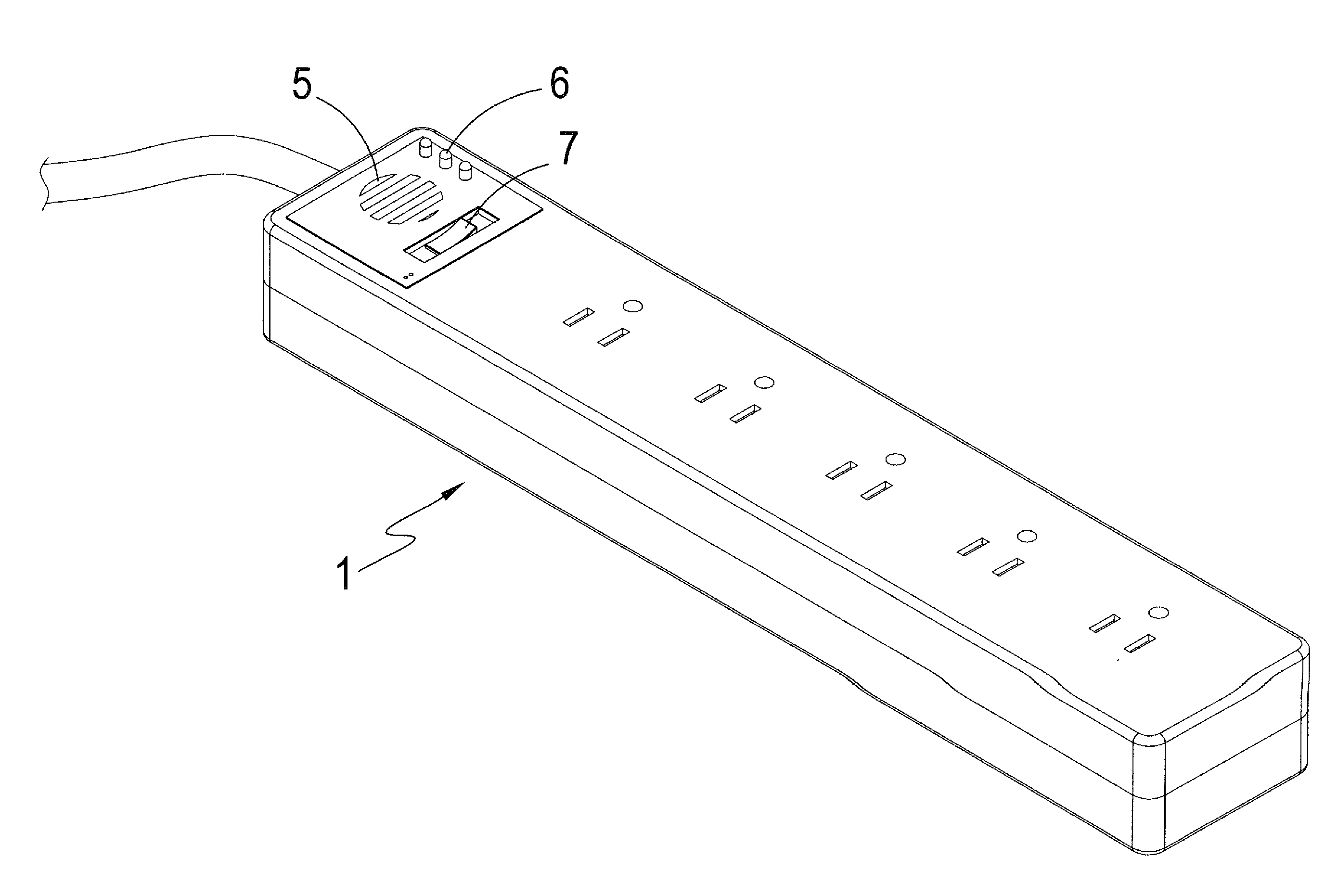
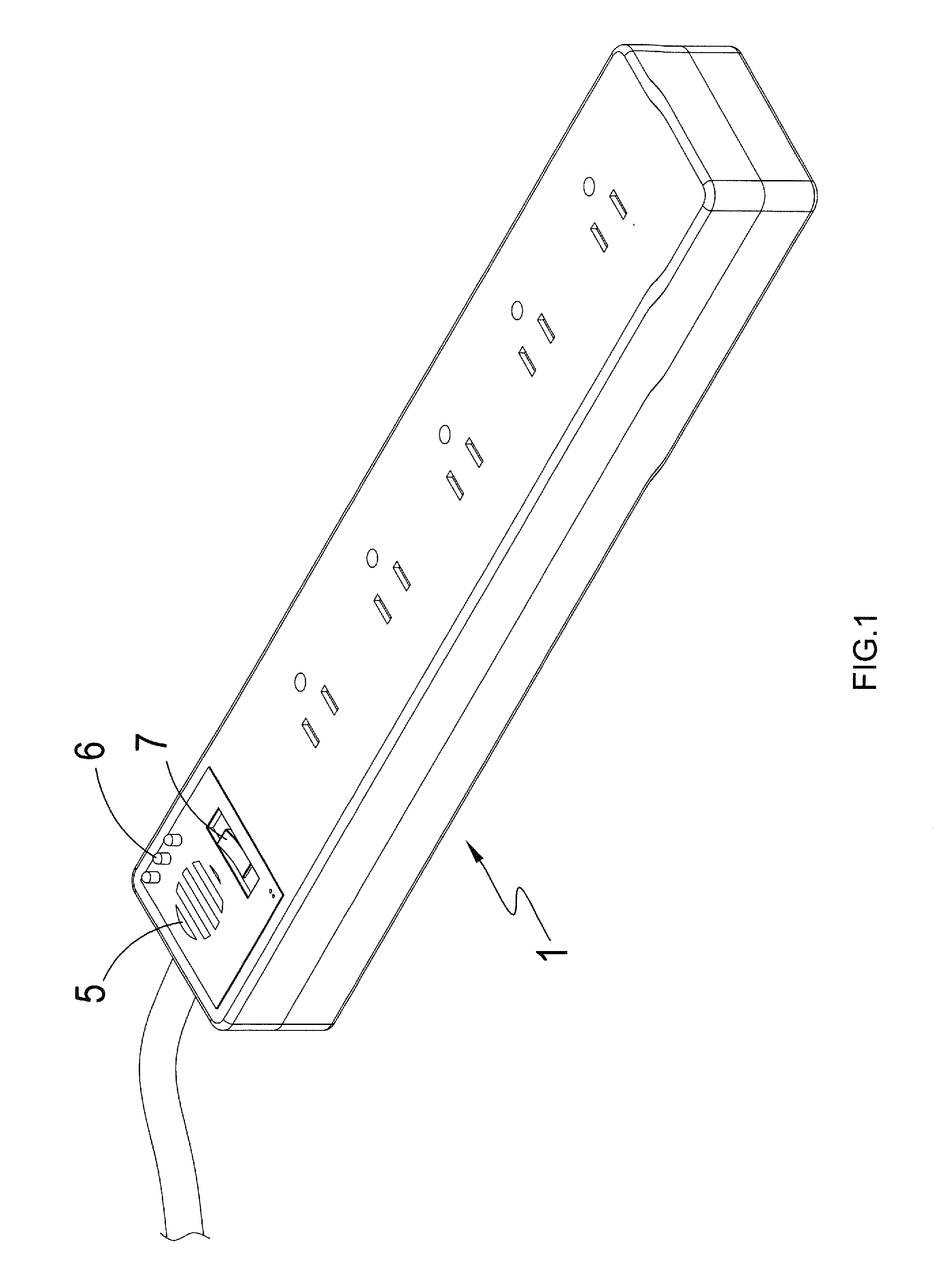
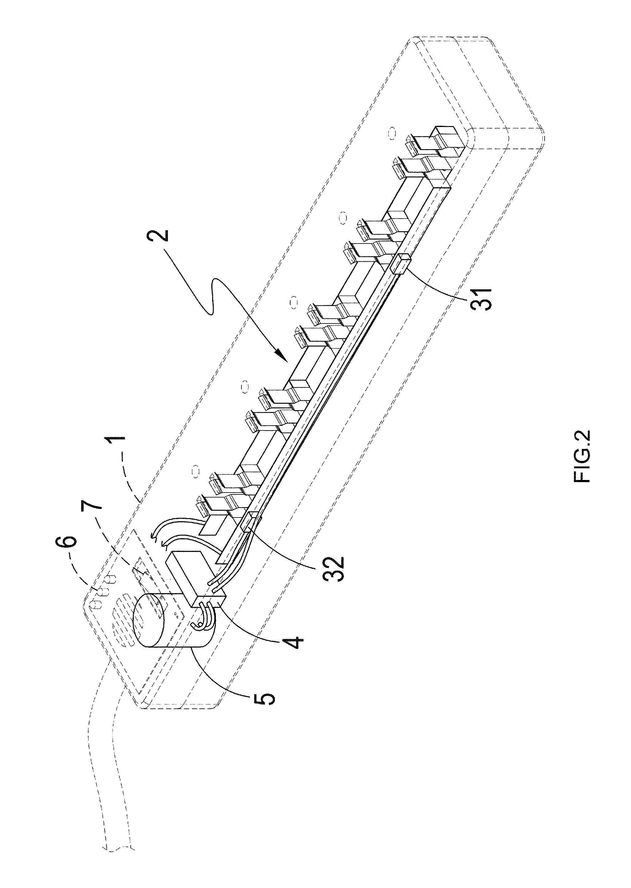
[0017]Referring to FIGS. 1, 2, and 3, which are respectively a perspective view showing a preferred embodiment of the present invention, a schematic view showing inside details of the preferred embodiment of the present invention, and a block diagram of the preferred embodiment of the present invention, the drawing clearly show that the present invention comprises:

[0018]a casing, wherein the casing 1 comprises a switch element 7 mounted to one side thereof;

[0019]a power socket module 2, which is rec...


PUM


Abstract

A power socket temperature alarm device includes a casing, a power socket module received in the casing, a plurality of temperature detection elements, a processing circuit module, at least a lighting alarm element, and at least a sound alarm element. The temperature detection elements are set in contact with the power socket module and the temperature detection elements are in information connection with the processing circuit module. The processing circuit module is operatively connected with the lighting alarm element (for indicating the site of a hazard) and the sound alarm element (for giving off a signal of the hazard). When the power socket module receives a plug inserted therein and supplies electrical power thereto, the temperature will be gradually increased and the temperature detection elements are separately activated. Status variation of the temperature detection elements activates the processing circuit module to give off flashing light and mutually different sounds.

Description

TECHNICAL FIELD OF THE INVENTION[0001]The present invention generally relates to a power socket including temperature-triggered audio alarm, and more particularly to a power socket temperature alarm device that provides multiple stages of safety alarm.DESCRIPTION OF THE PRIOR ART[0002]A power cord is generally a common name for a power extender that has a plug and multiple outlets in electrical connection with the plug or simply a length of a power cable, both being commonly considered belonging to the field.[0003]The earliest version of the power cord is simply an extension cable for the purposes of extending length and it has gradually evolved in the functionality thereof by including a switch, a one-to-multiple extender, a timer, a voltage / current display. All these help improve the functionality of the power cord, making the use thereof more and more convenient.[0004]In the known devices, a safety arrangement is often employed, wherein the physical property that heat will be gen...

Claims


Application Information

Patent Timeline
Patent Type & Authority Applications(United States)
IPC IPC(8): G08B21/18G08B7/06
CPCG08B7/06G08B21/182H01R2103/00G01K1/026G06F1/26H01R13/6683H01R13/6691H01R13/70H01R25/003G01K3/005G06F2200/261
Inventor YANG, WEI-LI
Owner YANG WEI LI
Learn More