Optimizing performance of a drilling assembly

a technology of drilling assembly and drilling performance, which is applied in the direction of adaptive control, borehole/well accessories, instruments, etc., can solve the problems of limiting this relationship, affecting the performance of drilling assembly, and rop generally increasing substantially linearly, so as to achieve continuous optimization of drilling performance and optimize drilling performance.

Active Publication Date: 2015-09-10
SHELL USA INC
View PDF11 Cites 31 Cited by
  • Summary
  • Abstract
  • Description
  • Claims
  • Application Information

AI Technical Summary

Benefits of technology

The invention is a system and method for optimizing the performance of drilling a borehole in an earth formation. It uses a self-tuning, multivariable controller that simultaneously maintains desired setpoints for multiple drilling variables and an optimization engine that manipulates the setpoints to continuously optimize drilling performance. The optimization engine evaluates several performance indicators, such as bit wear, cost, and energy efficiency, and uses these indicators to make adjustments to the controller setpoints. The method also includes a scanning procedure to evaluate the objective functions and a two-step or drill-off scanning algorithm to determine whether to stop or continue the scanning. Overall, this invention improves drilling performance by perturbing manipulated variables and assessing how controlled variables and objective functions change in response to those perturbations.

Problems solved by technology

Drilling performance is often quantitatively assessed in terms of cost per foot drilled (CPF) or average ROP over a hole section or a bit run, and is affected by uncontrollable and controllable factors.
For example, ROP generally increases substantially linearly with increased WOB, but there is a limit to this relationship, as the drilling process becomes inefficient at high values of WOB as a result of factors such as increased wear of the drill bit, bit balling, insufficient borehole cleaning, and drill string vibration.
Also, the drilling process may become inefficient at relatively low values of WOB, especially when drilling into hard geological formations.
Moreover, the transient effects on WOB, TOB and ROP caused by variations in formation characteristics and downhole conditions further complicate identification and maintenance of parameters that optimize the drilling performance of the drilling assembly.
Procedures for quantification of system response, such as step tests, are well known in the controls industry, but these can be time consuming and are not commonly applied as drilling progresses.
As a result, the ability of auto-drillers to hold setpoints is suboptimal, and “overshoot” of control variables can cause machine protection limits to be reached.
This interrupts the drilling process and forces the driller to intervene to correct the situation.
The lost time contributes to increased cost per foot and decreased average ROP.
These approaches are limited in that they (1) are time consuming, (2) require availability of offset data to calibrate models, (3) are only applicable over ranges of drilling parameters used in offset wells, (4) are heavily dependent on bit attributes that are difficult to ascertain and can vary widely from one design to another, and (5) are only marginally applicable to wells where different formations and / or different well trajectories are used.
These approaches are limited in usefulness because they are either (1) highly sensitive to noise in drilling data, and thus require considerable computational overhead; (2) ineffective because they require excessive time to implement, during which drilling is conducted using sub-optimal combinations of parameters; (3) incomplete because they do not effectively address constraints that should limit parameter selection, e.g. indications of dynamic dysfunction.

Method used


Image

  • Optimizing performance of a drilling assembly
  • Optimizing performance of a drilling assembly
  • Optimizing performance of a drilling assembly

Examples


Embodiment Construction

The System: Self-Tuning Multivariable Controller

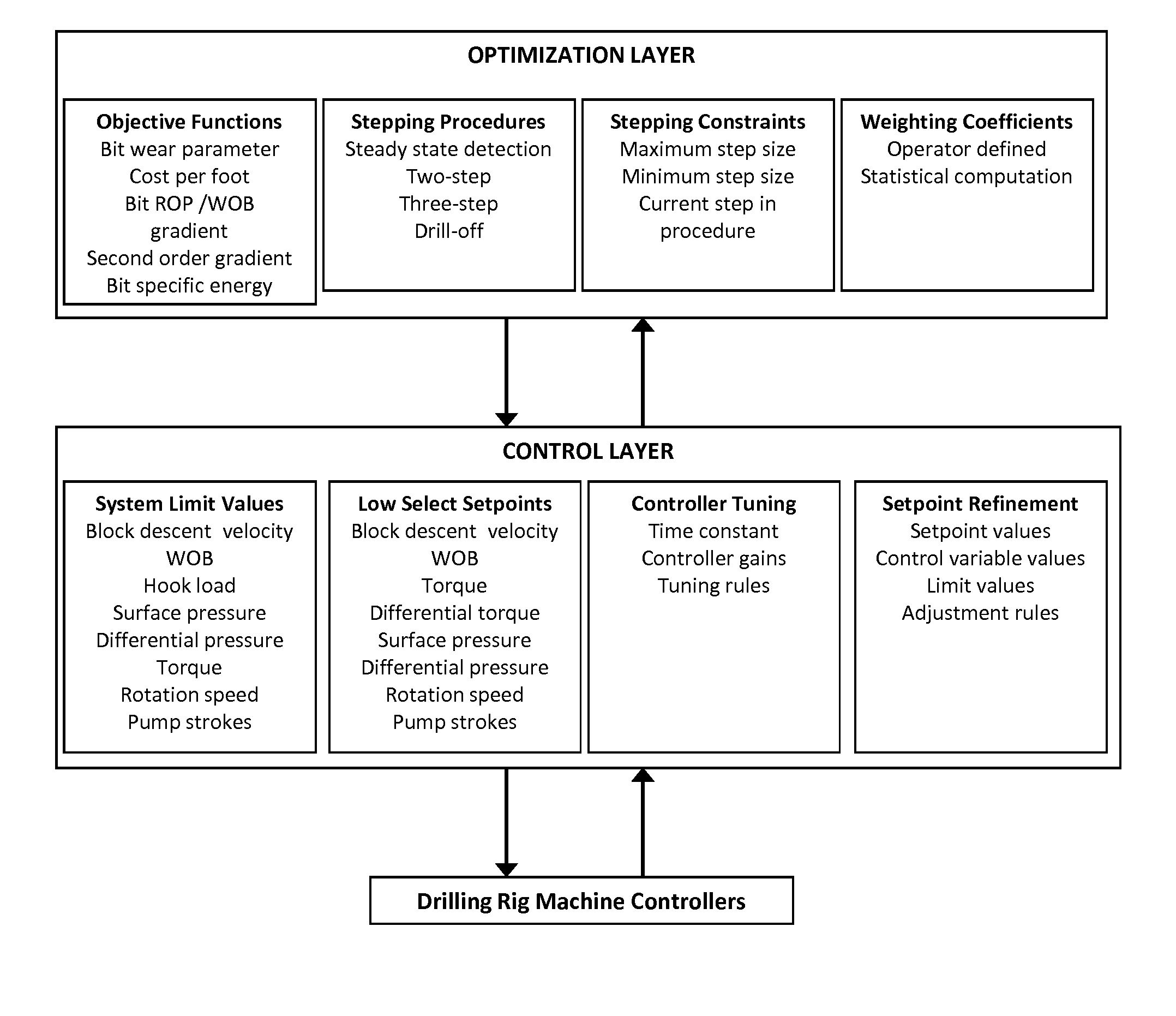
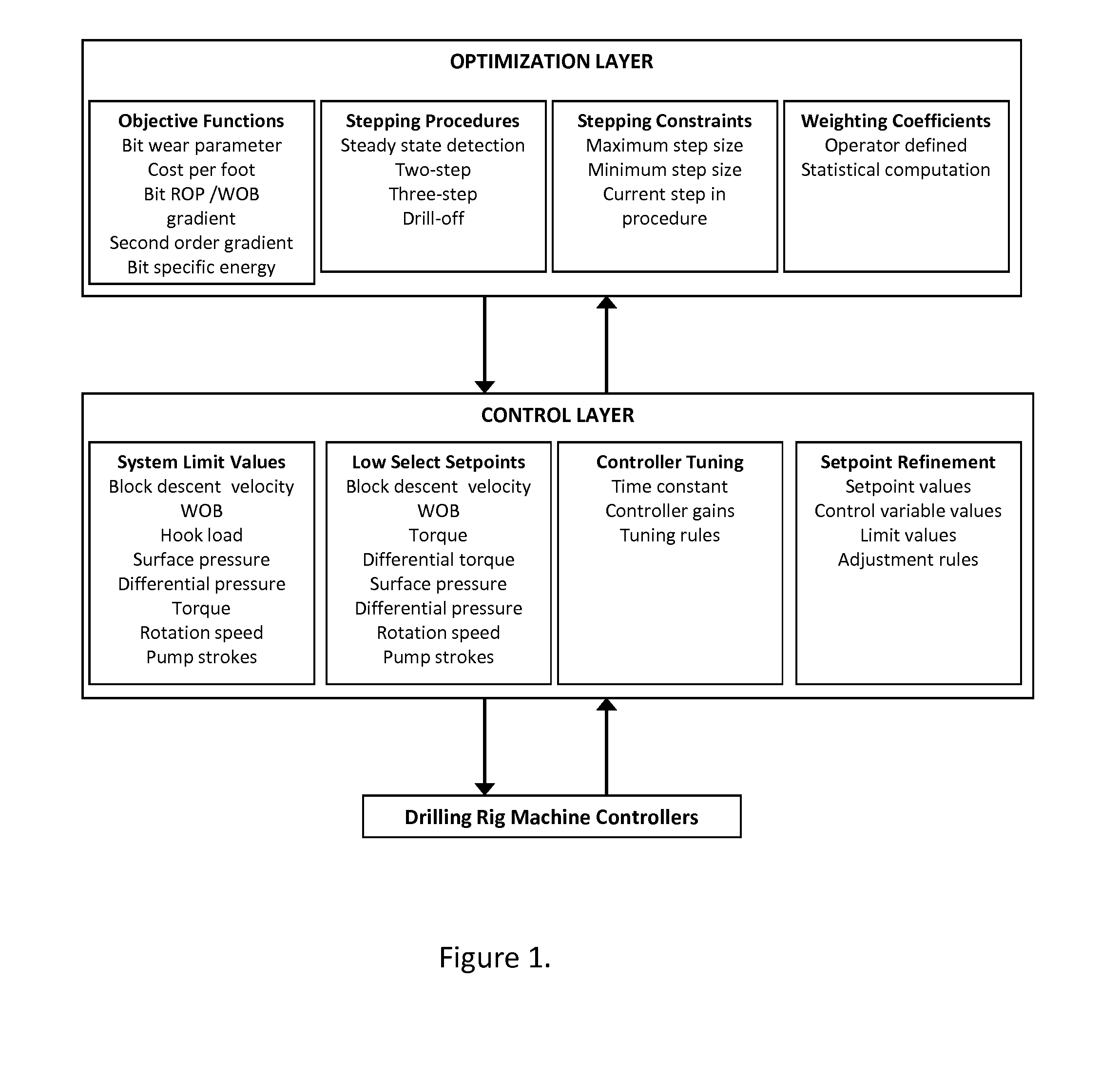
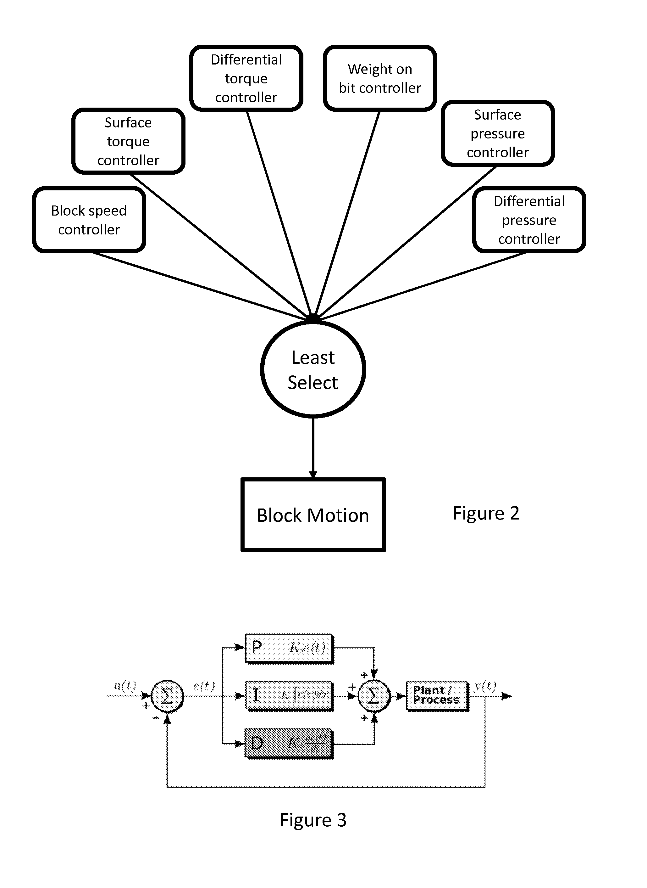
[0043]FIG. 1 presents a structural view of the drilling control and optimization system. The control layer comprises a self-tuning, multivariable controller that enables improved, simultaneous maintenance of desired setpoints for a number of drilling variables. FIG. 2 provides examples of variables that can be used as the basis for control. In a preferred embodiment, the controllers for each of these variables are of the proportional-integral-derivative (PID) type, a block diagram of which is provided in FIG. 3. The standard form of the governing equation for a PID controller is provided below.

z=KCe+KCTI∫0teτ+KCTDe.(1)

[0044]In the above equation z is the controller output, e is the error (defined as the setpoint minus the process variable value at the current time), KC is the controller gain, alternately known as the proportional gain, and TI and TD are time constants for integral and derivative terms, respectively. The integral time c...


PUM


Abstract

A system and method for optimized control of an assembly for drilling a borehole comprises a self-tuning, multivariable controller and an optimization engine that manipulates the setpoints of the controller such that drilling performance may be continuously optimized. The method includes evaluation of a characteristic system time constant, using this constant to compute bit ROP, using computed ROP to compute process gains, which are used to tune the multivariable controller, automatically refining controller setpoints based on controller performance, and using an optimization engine to systematically adjust controller setpoints such that drilling parameters are optimized based on any of several performance indicators, or a weighted combination of performance indicators. The method further comprises using at least one performance indicators which may be computed using estimated bit ROP: bit wear parameter; gradient of cost per foot; gradient of bit ROP versus WOB; simplified mechanical specific energy; and hydraulic specific energy.

Description

TECHNICAL FIELD OF THE INVENTION[0001]The present invention relates to a system and method for optimizing the drilling performance of a drilling assembly for drilling a borehole in an earth formation.BACKGROUND OF THE INVENTION[0002]Wellbores are generally drilled using a drilling rig that supports and rotates a drill string having a drill bit at its lower end. Drilling rigs employ either a block and tackle or hydraulic means to raise and lower the drillstring, and may employ a rotary table or a top drive to rotate the drillstring. Fluid is circulated through the drillstring and bit to clean the bit and wellbore. A downhole motor or turbine is sometimes used near the bit to allow drilling to progress with or without rotation of the drillstring at the surface; for example, when directional drilling operations are conducted.[0003]The drillstring initially hangs in tension with its weight supported by a hook on the travelling portion of the suspension system. The hook also supports the...

Claims


Application Information

Patent Timeline
IPC IPC(8): E21B44/04G05B13/02
CPCG05B13/021E21B44/04E21B21/08G05B13/04
Inventor ASTRID, PATRICIASINGH, ABHAY KUMARHUHMAN, JOHN EDWARDSTOEVER, MATTHEW ALANDYKSTRA, MARK WILLIAMGRAUWMANS, ROB HENDRIKUS GERARDUS MARINUSBLANGE, JAN-JETTE
Owner SHELL USA INC
Why Eureka
Try Eureka