
Turbo-Compressor System and Method for Extracting Energy from an Aircraft Engine

Active Publication Date: 2015-09-10
THE BOEING CO
View PDF10 Cites 70 Cited by
  • Summary
  • Abstract
  • Description
  • Claims
  • Application Information

AI Technical Summary

Benefits of technology

The improved aircraft system and method described in the patent text may provide significant advantages over existing systems and methods. It includes a turbo-compressor system that extracts energy from bleed air to reduce the amount of bleed air needed for an air conditioning system, which in turn reduces power requirements for the aircraft. The system also uses the extracted energy to compress ram air, resulting in reduced temperature pack inlet air and reduced air conditioning pack ram air usage. Overall, the technical effects of this system include improved efficiency, reduced power requirements, and improved air conditioning performance.

Problems solved by technology

However, in known bleed based aircraft air conditioning systems, the pneumatic energy or power extracted from the bleed air provided by the bleed air system of the aircraft engine to the aircraft air conditioning system may be decoupled and not aligned with the power or energy needed by the aircraft air conditioning system to meet its flow and cooling demands.
Such excess power may result in inefficiency and wasted energy.
Because the aircraft air conditioning system is typically the largest energy user on the aircraft, other than the propulsion of the aircraft itself, such wasted energy may represent a significant fuel burn impact to the aircraft.
Increased pack ram air usage, and in turn, increased ram air flow, may result in increased ram air drag to the aircraft.

Method used


Image

  • Turbo-Compressor System and Method for Extracting Energy from an Aircraft Engine
  • Turbo-Compressor System and Method for Extracting Energy from an Aircraft Engine
  • Turbo-Compressor System and Method for Extracting Energy from an Aircraft Engine

Examples


Embodiment Construction

[0032]Disclosed embodiments will now be described more fully hereinafter with reference to the accompanying drawings, in which some, but not all of the disclosed embodiments are shown. Indeed, several different embodiments may be provided and should not be construed as limited to the embodiments set forth herein. Rather, these embodiments are provided so that this disclosure will be thorough and will fully convey the scope of the disclosure to those skilled in the art.

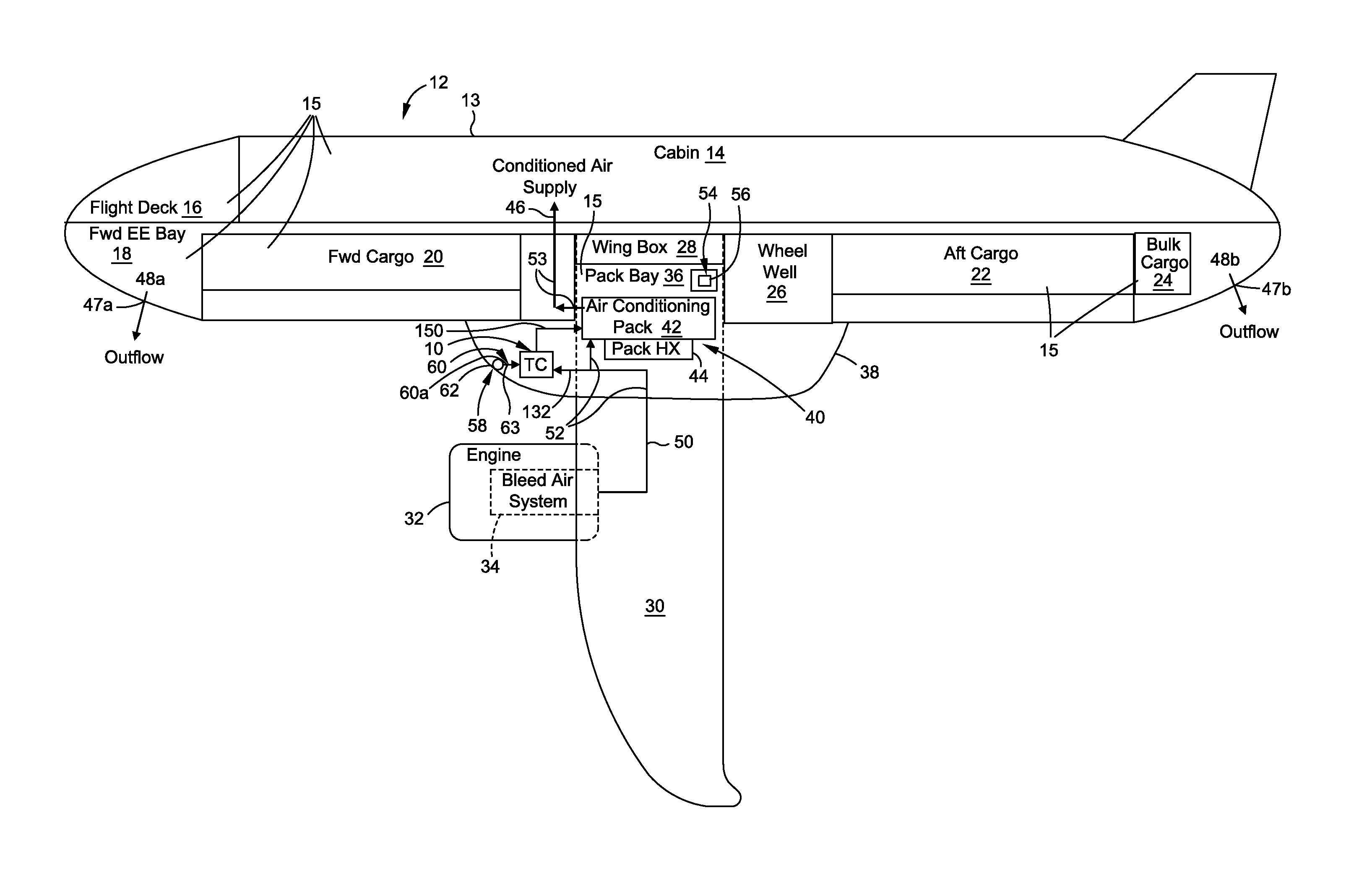
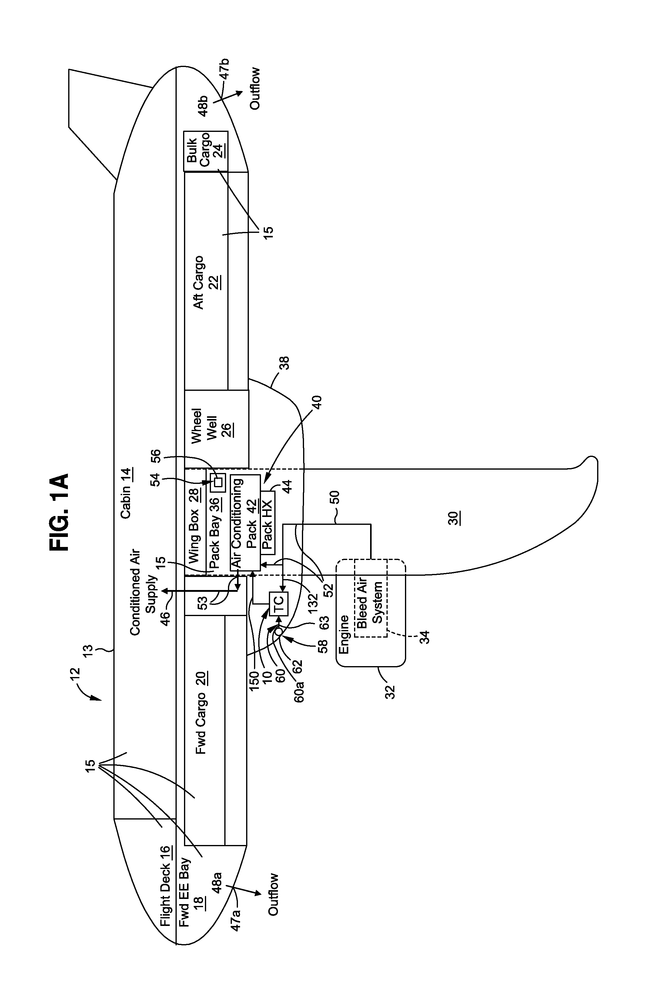
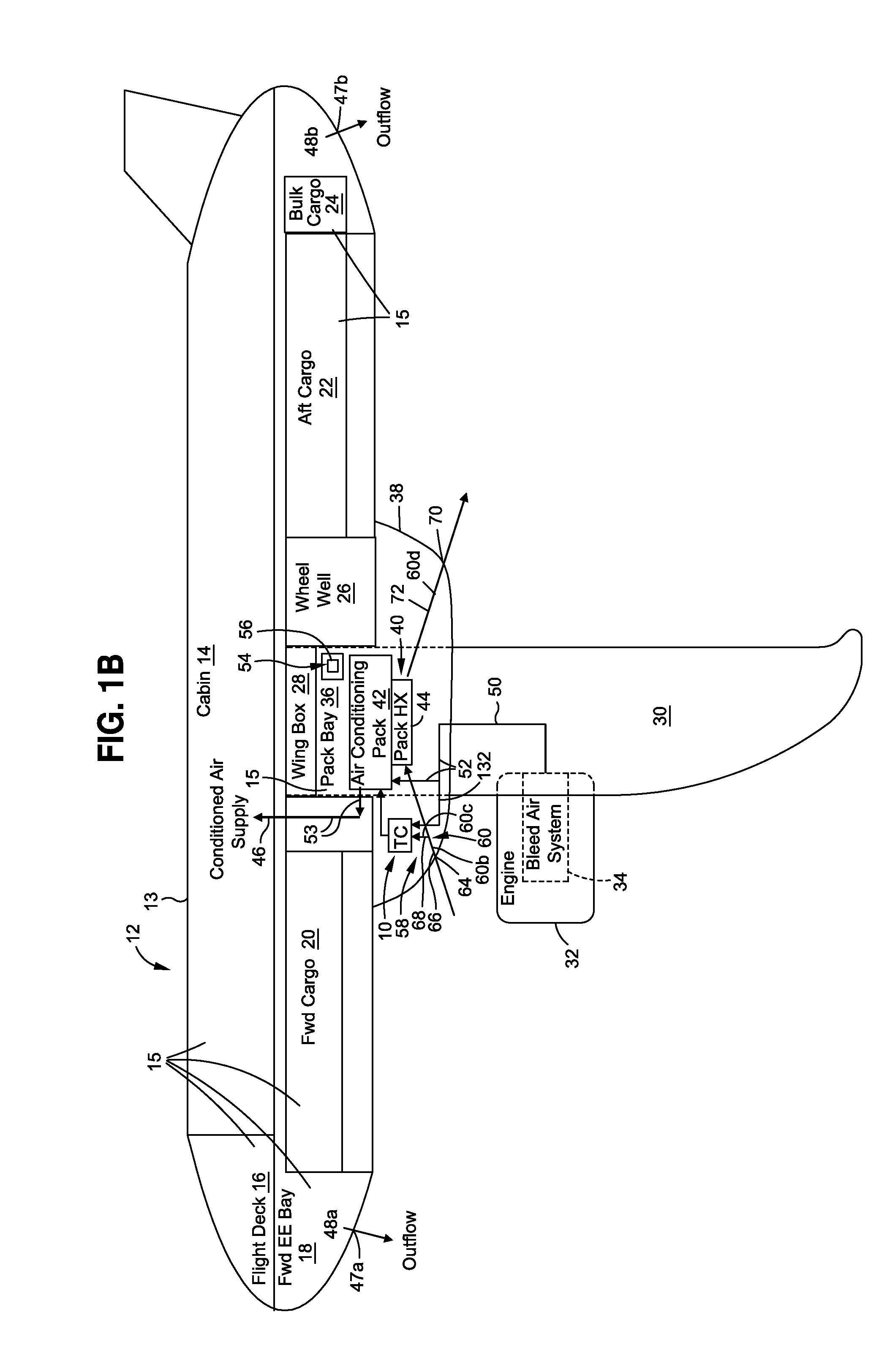
[0033]Now referring to the Figures, FIG. 1A is an illustration of a schematic diagram of an aircraft 12 having an embodiment of a turbo-compressor (TC) system 10 of the disclosure with one embodiment of a ram air inlet 58. FIG. 1B is an illustration of a schematic diagram of an aircraft 12 having an embodiment of a turbo-compressor system 10 of the disclosure with another embodiment of a ram air inlet 58. The turbo-compressor system 10 (see FIGS. 1A-8), discussed in detail below is designed to extract energy from bleed...


PUM


Abstract

A turbo-compressor (TC) system for extracting energy from an aircraft engine. The TC system has a TC assembly with a turbine mechanically coupled to at least one compressor. The TC system has a TC inlet in fluid communication with a bleed air system in the aircraft engine and a TC outlet in fluid communication with an air conditioning (AC) pack of an aircraft air conditioning system and configured to extract reduced temperature pack inlet air from the TC assembly into the air conditioning pack. The TC system has a ram air inlet coupled to the at least one compressor. The TC system has a TC control valve, and a TC check valve or a TC shutoff valve, both coupled to the TC assembly via a plurality of connective ducts. The TC system extracts energy from the bleed air to reduce bleed air flow and AC pack ram air usage.

Description

BACKGROUND[0001]1) Field of the Disclosure[0002]The disclosure relates generally to aircraft air conditioning systems and methods, and more particularly, to aircraft air conditioning systems and methods for extracting energy from an aircraft engine in a bleed air based aircraft air conditioning system.[0003]2) Description of Related Art[0004]Known air conditioning systems used in transport vehicles, such as commercial aircraft, typically use an air based thermodynamic cycle to provide cool, pressurized air to various interior compartments of the aircraft, such as the passenger cabin, cargo compartments, and other interior compartments. Air from the compressor stages of the main aircraft engines, typically referred to as “bleed air”, may be bled by a bleed air system from two or more of such aircraft's gas turbine engines to supply pneumatic power to various aircraft and engine systems. For example, bleed air may be used to supply pneumatic power to the aircraft air conditioning syst...

Claims


Application Information

Patent Timeline
IPC IPC(8): B64D13/08B64D41/00F25B31/02F02C7/32F25B27/00
CPCB64D13/08F02C7/32F25B27/00B64D2013/0688B64D41/007B64D2013/0618B64D2013/0644F25B31/026B64D13/06B64D2013/0648Y02T50/50
Inventor ATKEY, WARREN A.
Owner THE BOEING CO
Learn More