Machine tool

a machine tool and tool magazine technology, applied in the field of sanding machines, can solve the problems of limiting the number of tool holders and thus the intake capacity of tool magazines

Active Publication Date: 2015-09-10
ADELBERT HAAS GMBH
View PDF9 Cites 8 Cited by
  • Summary
  • Abstract
  • Description
  • Claims
  • Application Information

AI Technical Summary

Problems solved by technology

This clear sector limits the number of tool holders and thus the intake capacity of the tool magazine.

Method used


Image

  • Machine tool
  • Machine tool
  • Machine tool

Examples


Embodiment Construction

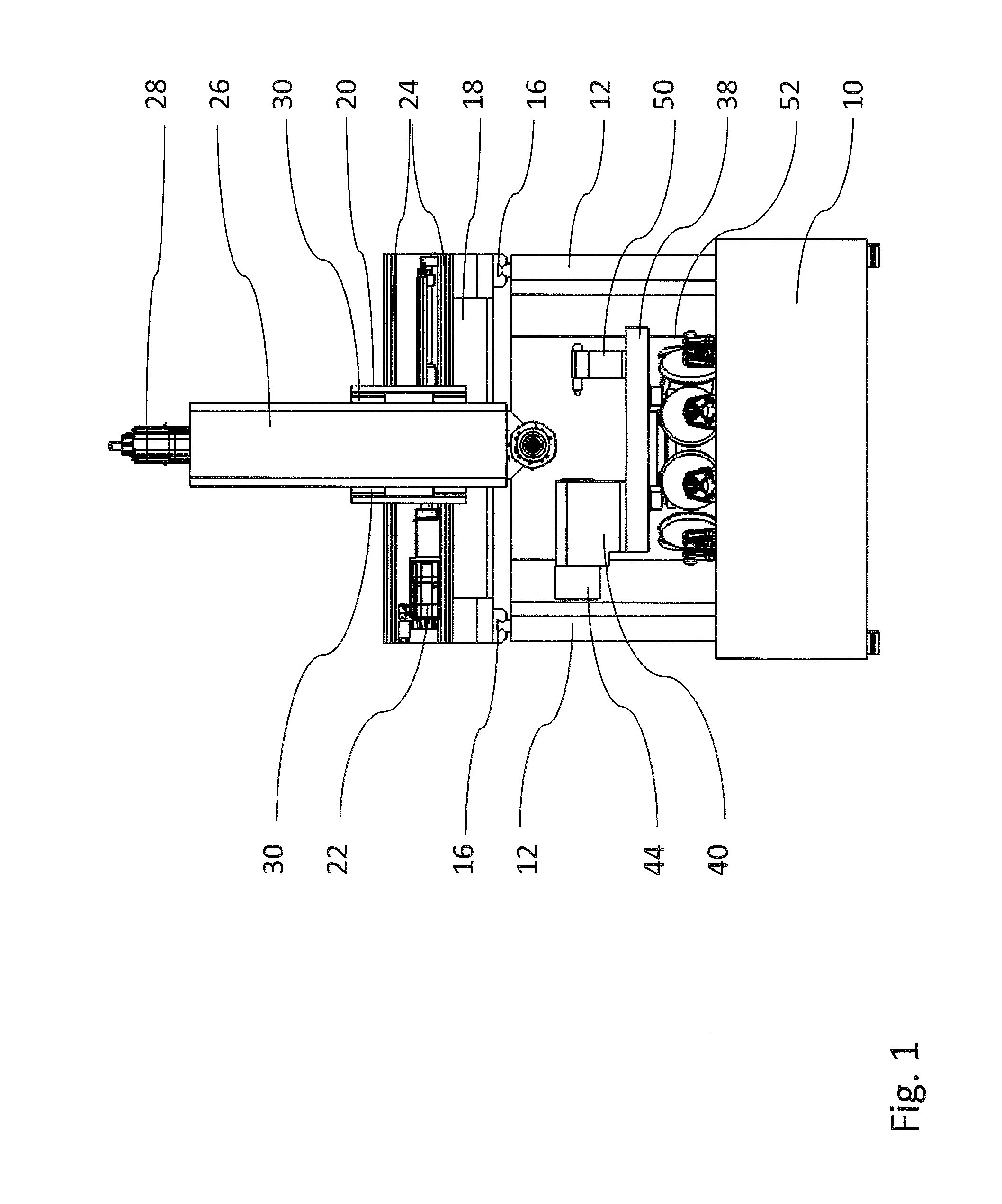
[0038]The essential concept of the invention comprises arranging the tool magazine, embodied as a magazine wheel, underneath the machine table. This way, the tool magazine requires no additional floor space. The floor space required of the sander is no greater than that of a sander without a tool magazine. The tool magazine is accessible for the exchange of tools, because it projects with its exchange position laterally beyond the machine table. This way, the sanding spindle can travel in the Z-axis past the machine table to-wards the bottom into the tool holder located respectively in the exchange position, in order to insert a tool or to accept one therefrom.

[0039]In an advantageous embodiment the machine table carrying the tool clamping device is rotational about the vertical C-axis. This allows the pivoting of the work piece clamped to the machine table in reference to the tool, preferably a sanding disk, clamped in the sanding spindle, in order to perform a four-axial sanding. ...


PUM


Abstract

A sanding machine, with a machine bed, two vertical supports arranged laterally at the machine bed, with a bridge displaceable on the vertical supports in a horizontal, linear Y-axis, with an X-sled displaceable at the bridge in a horizontal, linear X-axis, with a Z-sled displaceable at the X-sled in a vertical, linear Z-axis, with an operating spindle supported at the Z-sled, particularly a sanding spindle, with a machine table and a magazine wheel comprising tool holders for sanding disks, and which is rotational about an axis parallel in reference to the Z-axis, with the operating spindle being able to remove a tool from a tool holder and place it there when this tool holder is rotated into an exchange position, with the tool magazine being arranged underneath the machine table and in the area of the exchange position.

Description

CROSS REFERENCE TO RELATED APPLICATIONS[0001]This patent application claims priority to German Patent Application 10 2014 102 938.0, filed on Mar. 5, 2014.STATEMENT REGARDING FEDERALLY SPONSORED RESEARCH OR DEVELOPMENT[0002]No federal government funds were used in researching or developing this invention.NAMES OF PARTIES TO A JOINT RESEARCH AGREEMENT[0003]Not applicable.SEQUENCE LISTING INCLUDED AND INCORPORATED BY REFERENCE HEREIN[0004]Not applicable.BACKGROUND[0005]1. Field of the Invention[0006]The present invention relates to a sanding machine.[0007]2. Background of the Invention[0008]A processing machine, particularly a sander in the Gantry design, shows two vertical supports, arranged laterally at the machine bed, on which a bridge can be displaced in a first horizontal, linear axis, numerically controlled. A sled, numerically controlled, is displaceable at this bridge in a second horizontal axis, orthogonal in reference to the first axis. Another sled is supported in a vertic...

Claims


Application Information

Patent Timeline
Patent Type & Authority Applications(United States)
IPC IPC(8): B24B27/00B23Q3/157
CPCB23Q3/15706B24B27/0061B23Q1/012B23Q3/15733B24B3/34B24B5/02B24B7/005Y10T483/1705Y10T483/174Y10T483/1882Y10T483/1795
Inventor BRAUN, HANS-DIETER
Owner ADELBERT HAAS GMBH
Why Eureka
Try Eureka