
Cellular Antenna Tower and Equipment Enclosure Based on Shipping Container

a technology of equipment enclosure and antenna tower, which is applied in special buildings, parkings, building repairs, etc., can solve the problems of conventional cell towers, towers installed in their neighborhoods, and unwillingness of building and land owners to lease the required space, so as to achieve convenient and cost-effective exterior cladding, increase the height, and the effect of increasing stability

Inactive Publication Date: 2015-08-27
WALTON CHADWICK J
View PDF0 Cites 4 Cited by
  • Summary
  • Abstract
  • Description
  • Claims
  • Application Information

AI Technical Summary

Benefits of technology

The solution provides a structurally strong, weather-tight, and cost-effective cell site structure that blends with the environment, reducing installation time and costs, and mitigates icing hazards, while allowing for easy maintenance and access, thus addressing the challenges of conventional cell towers.

Problems solved by technology

While there is a high and growing demand for cellular telephone and other wireless communication services, many people object to the appearance of conventional cell towers and do not want such towers installed in their neighborhoods or areas where the view is important.
Thus, wireless service providers are faced with a dilemma: they must install additional cell sites if they wish to improve and expand their wireless coverage and their range of wireless services to satisfy customer demand; but they are often faced with strong public objection, unwillingness of building and land owners to lease the required space, and local zoning restrictions against erecting additional cell towers in the areas where they are needed to satisfy the local demand for wireless service.
However, such outdoor certified equipment packages come at a much higher cost, approximately double, compared to the cost of indoor type equipment.
The ever increasing number of cellular telephones and other mobile wireless devices communicating via cellular networks is overburdening the available capacity of the existing cell cites.
Namely, each cell site has a limited number of channels available and can thus handle only a limited number of simultaneous calls or communications, and each channel has a limited bandwidth i.e. a limited rate of data transfer.
This becomes problematic for several reasons.
Most conventional cell towers are generally regarded as visually unattractive because they clutter or interrupt the existing skyline with unfamiliar or harsh-looking mechanical structures.
Also, some building codes, zoning ordinances and other local ordinances prohibit the erection of such a tower or any structure that does not blend-in or conform to existing or specified architectural styles and appearances.
However, such camouflage or concealment efforts give rise to significant additional costs in the design and installation of the cell tower, as well as additional legal costs in obtaining the necessary local zoning and building permit approval.
The process of obtaining community acceptance as well as local zoning or building permit approval also adds significant time delay to the planning and installation of a new cell site.
However, such installations on an existing building often require re-engineering and structural modifications of the existing building to support the added load of the cellular communication facilities and to achieve a stealthy concealment thereof without blocking the wireless transmission and reception of the antennas.
That causes potential problems for the building owner, and also gives rise to liability issues if the installed facilities or any maintenance access cause damage (e.g. a leaking roof) to the existing building.
Even in rural areas where free-standing cell towers are more common than cell sites installed in existing buildings, typical cell towers are still considered unattractive.
Because cell towers are generally located relatively close to populated or well-traveled areas (e.g. along a highway) even in rural areas, a typical cell tower may be objectionable because it mars the otherwise pristine natural beauty of the surrounding rural landscape.
In addition to an unattractive appearance, conventional cell towers suffer a significant problem of icing during the winter in northern climes.
Furthermore, when the tower is subjected to any wind load bending or swaying, or the metal warms slightly due to changed weather conditions, then the accumulated ice breaks off and falls down from the tower truss members.
The falling ice is a significant hazard to any persons and equipment in the area at the base of the tower.
Because this falling ice has been known to damage equipment shelters, it is therefore necessary to build the equipment shelters stronger to resist the icefall damage and protect the equipment within.
Occasionally, cellular equipment shelters and the equipment housed therein are also damaged by gunshots fired at the cellular facility.
Such a concrete bunker is extremely heavy, and requires specialized heavy lift crane equipment or heavy lift helicopters for placement on site.
A given shipping container is often used several times for bi-directional shipping of different goods back and forth between two locations, or for sequential shipping of different goods from point A to point B, then from point B to point C, then from point C to point D, and then perhaps back to point A. However, when the balance of trade, or especially the balance of shipments into and out of a given location is unbalanced and involves a greater number of inbound shipments than outbound shipments, this results in stockpiling of empty shipping containers at such a location.

Method used


Image

  • Cellular Antenna Tower and Equipment Enclosure Based on Shipping Container
  • Cellular Antenna Tower and Equipment Enclosure Based on Shipping Container
  • Cellular Antenna Tower and Equipment Enclosure Based on Shipping Container

Examples


Embodiment Construction

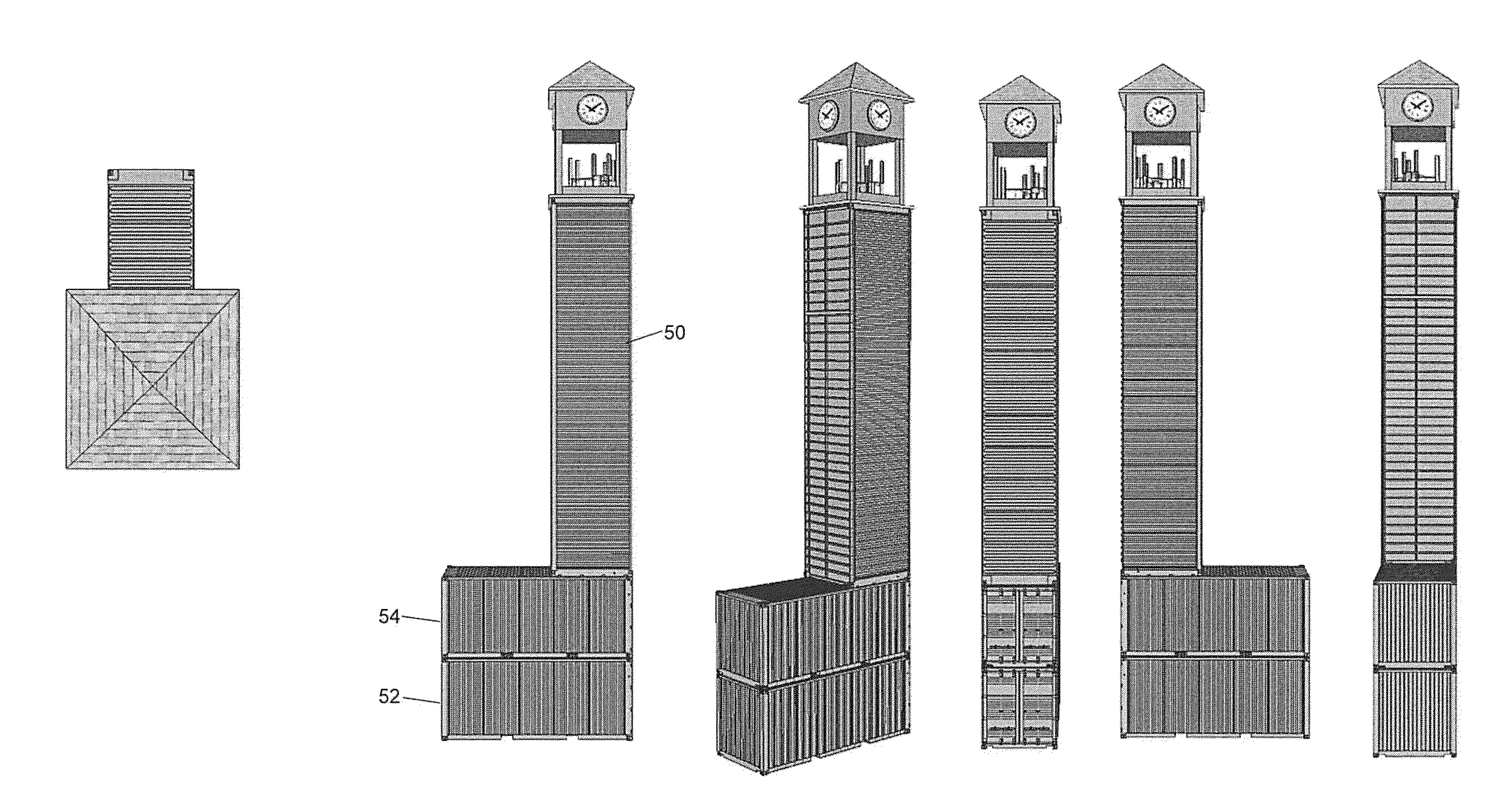
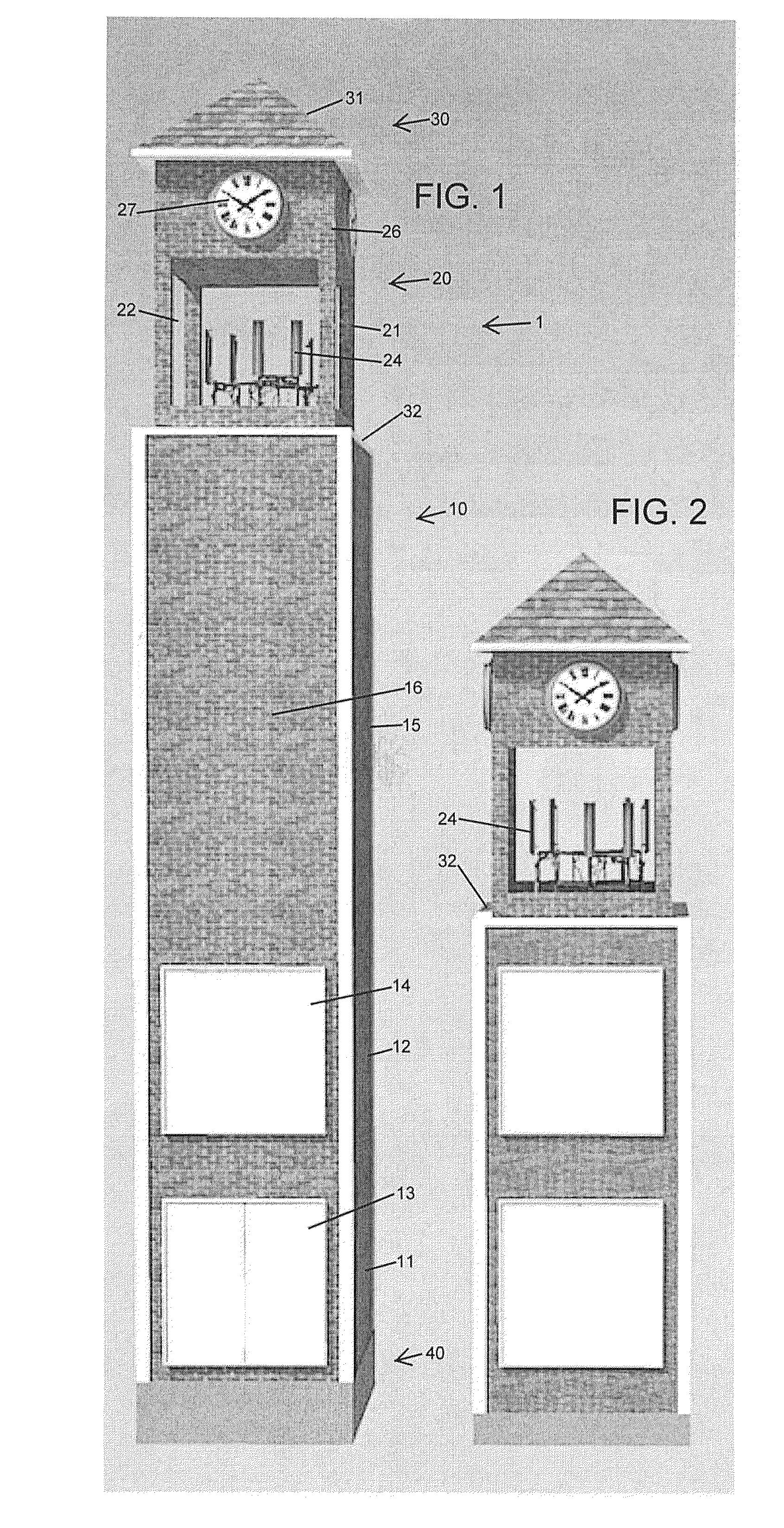
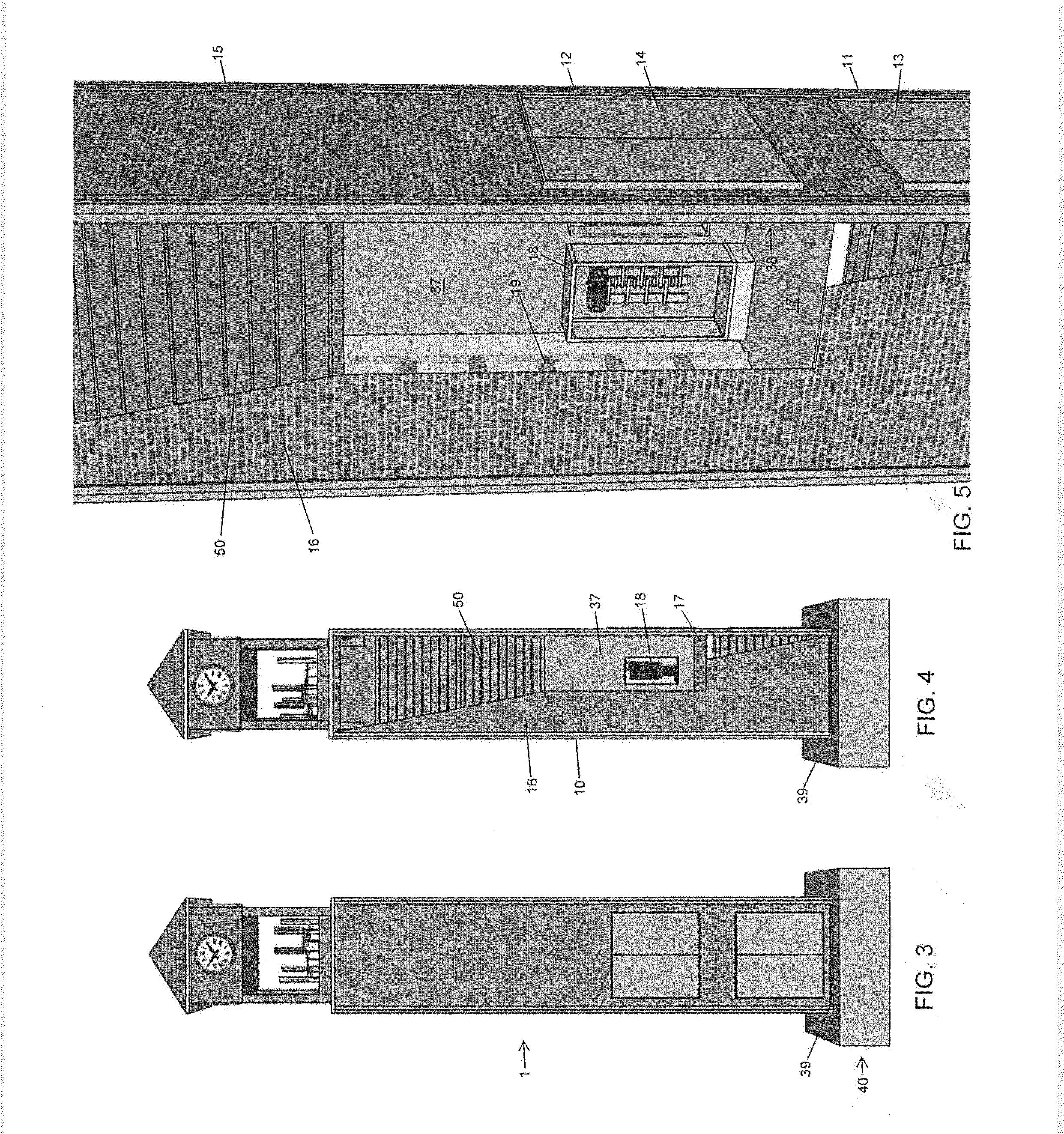
[0048]As shown in FIG. 1, for example, a cell site structure or antenna tower structure 1 according to the invention generally includes a tower 10 mounted on a foundation 40, and carrying an antenna cupola 20 on top of the tower 10. The antenna cupola 20 includes a cupola frame structure 21 that is preferably constructed of non-metallic materials, and most preferably completely of composite materials, so that the cupola frame structure 21 does not cause any reflection, blocking, interference or other degradation of the wireless signals of one or more antennas 24 mounted in at least one antenna stage 22 of the antenna cupola 20. This single antenna stage or first antenna stage 22 has large openings respectively between four cupola legs of the frame 21 at the corners forming the perimeter of the cupola, to provide unobstructed beam patterns, preferably in all four directions, for the antennas 24 forming one or more rad centers in the antenna stage 22. The antennas 24 may be any type o...


PUM


Abstract

An antenna tower structure for wireless communication antennas includes an antenna cupola mounted on a tower based on at least one standardized ISBU shipping container that has been modified and erected to stand upright on a foundation. The modifications may include longitudinal reinforcements along at least two longitudinal edges of the container, mounting hardware at the two ends of the container, an access door on a side of the container, an access hatch in the upper end of the container, a ladder extending longitudinally inside the container, and a floor extending perpendicular to the longitudinal axis of the container. The container provides a weather-protected climate-controlled interior space for sheltering electronics equipment. The cupola has antennas installed on at least one level, and may include shutters, a clock, a bell etc. to hide the antennas and disguise the tower. The exterior of the structure may be finished to match surrounding buildings.

Description

CROSS-REFERENCE TO RELATED APPLICATION[0001]This application is a Continuation and claims the benefit under 35 USC 120 of U.S. patent application Ser. No. 13 / 844,745 filed on Mar. 15, 2013, to be issued on Feb. 10, 2015 as U.S. Pat. No. 8,950,158, the entire disclosure of which is incorporated herein by reference.FIELD OF THE INVENTION[0002]The invention relates to a structure that serves as a tower for mounting wireless communication antennas and sheltering associated wireless communication base station equipment, as well as a method of deploying such a structure.BACKGROUND INFORMATION[0003]So-called “cell towers” have become ubiquitous in urban, suburban and rural areas in the United States and around the world. While there is a high and growing demand for cellular telephone and other wireless communication services, many people object to the appearance of conventional cell towers and do not want such towers installed in their neighborhoods or areas where the view is important. Th...

Claims


Application Information

Patent Timeline
Patent Type & Authority Applications(United States)
IPC IPC(8): H01Q1/12E04H12/34H01Q1/44
CPCH01Q1/12E04H2001/1283E04H12/342H01Q1/44
Inventor WALTON, CHADWICK J.
Owner WALTON CHADWICK J
Learn More