Substrate processing apparatus and substrate processing method

Active Publication Date: 2015-08-27
DAINIPPON SCREEN MTG CO LTD
View PDF5 Cites 330 Cited by
  • Summary
  • Abstract
  • Description
  • Claims
  • Application Information

AI Technical Summary

Benefits of technology

[0076]The controller performs the uniform heating step and the temperature difference generating step. In the uniform heating step, the substrate is heated uniformly at a temperature equal to or higher than the boiling point of the processing liquid. This causes a gaseous phase to be formed between the liquid film, of the processing liquid and the upper surface of the substrate. In the temperature difference generating step, a high-temperature region and a low-temperature region having their respective different temperatures are formed in the upper surface of the substrate. This generates a temperature difference in the liquid film of the processing liquid, and a flow toward the lower temperature is formed in the liquid film of the processing liquid. With this generation of temperature difference, an outward flow toward the peripheral portion of the substrate is formed in the liquid film of the processing liquid, so that the liquid film of the processing liquid on the substrate is removed from the

Problems solved by technology

In such a spin drying step, it may not be possible to sufficiently remove rinse liquid getting into a pattern formed on the substrate, which may result in poor drying.
In such a conventional spin drying step, two adjacent patterns may be attracted to ea

Method used


Image

  • Substrate processing apparatus and substrate processing method
  • Substrate processing apparatus and substrate processing method
  • Substrate processing apparatus and substrate processing method

Examples


first preferred embodiment

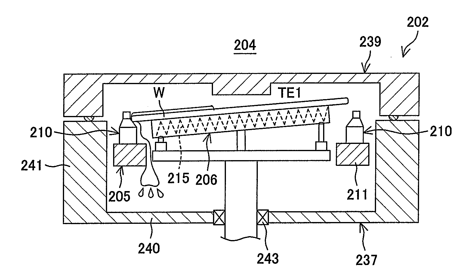
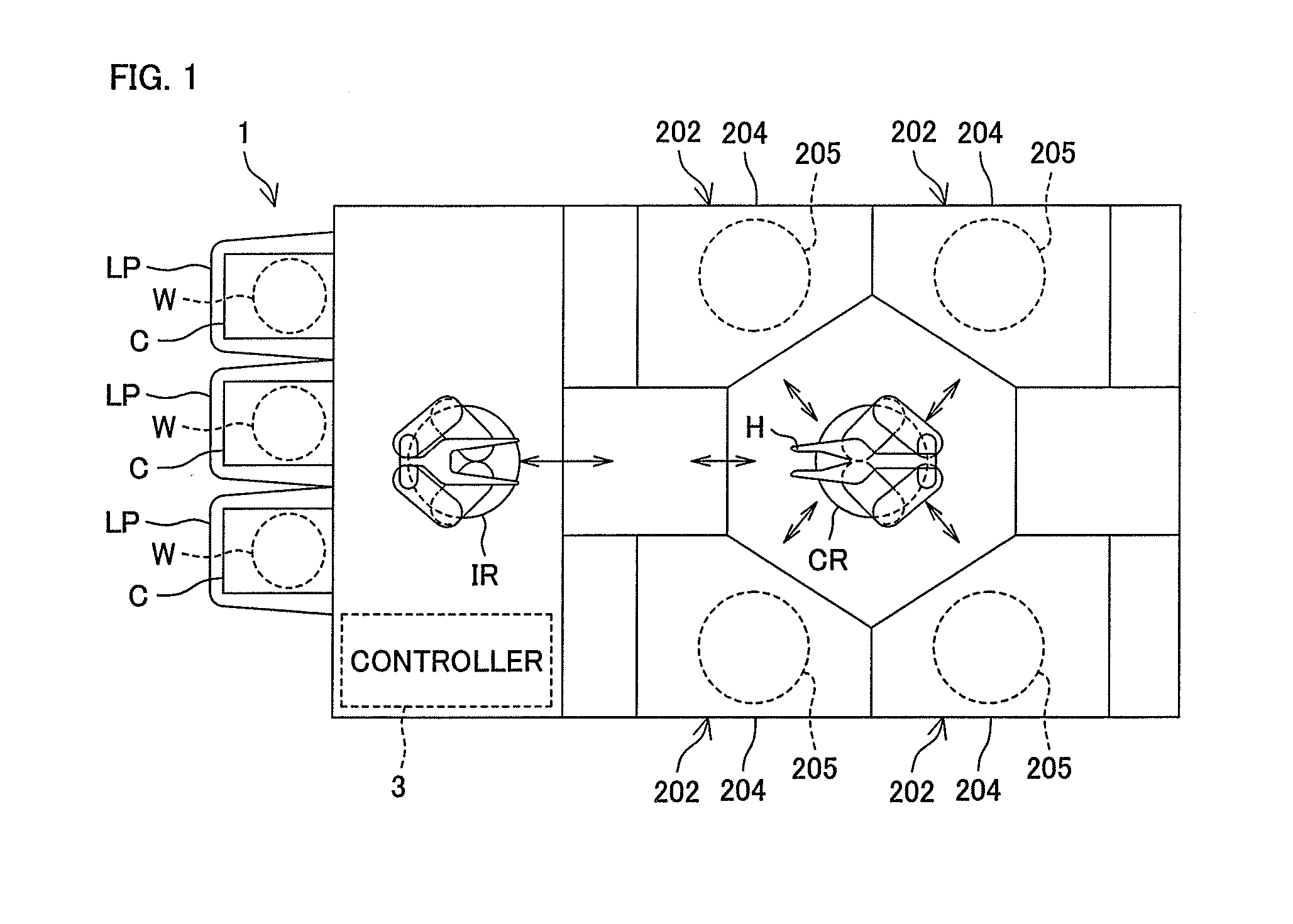
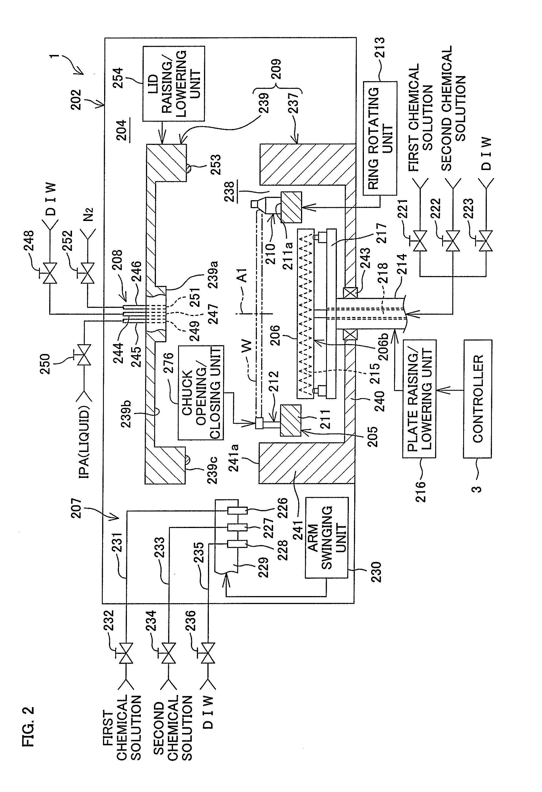
[0160]FIG. 1 is a schematic plan view of a substrate processing apparatus 1 according to a first preferred embodiment of the present invention. FIG. 2 is a schematic vertical cross-sectional view of a processing unit 202 included in the substrate processing apparatus 1 shown in FIG. 1.

[0161]The substrate processing apparatus 1 is a single substrate processing type in which disk-shaped substrates W such as silicon wafers are processed one by one. As shown in FIG. 1, the substrate processing apparatus 1 includes multiple processing units 202 arranged to process the substrates W with processing liquid, load ports LP on which carriers C are placed to house the respective multiple substrates W to be processed in the processing units 202 therein, delivery robot IR and delivery robot CR arranged to deliver the substrates W between the load ports LP and the processing units 202, and a controller 3 arranged to control the substrate processing apparatus 1.

[0162]The processing units 202 are si...

second preferred embodiment

[0351]Next will be described a second preferred embodiment of the present invention. In FIG. 22 and the following figures, components equivalent to those shown in FIGS. 1 to 21 are designated by the same reference symbols as in, for example, FIG. 1 and description thereof shall be omitted.

[0352]As shown in FIG. 22, the processing unit 2 includes a first substrate holding unit 15 arranged to rotate a substrates W about a vertical axis of rotation A1 passing through the center of the substrate W while keeping the substrate W in a horizontal attitude and a second substrate holding unit 29 arranged to heat the substrate W while keeping the substrate W in a horizontal attitude. The first substrate holding unit 15 and the second substrate holding unit 29 are examples of the substrate holding unit.

[0353]As shown in FIG. 22, the processing unit 2 further includes an openable / closable inner chamber 7 to house the first substrate holding unit 15 and the second substrate holding unit 29 therei...


PUM

PropertyMeasurementUnit
Temperatureaaaaaaaaaa
Lengthaaaaaaaaaa
Circumferenceaaaaaaaaaa

Abstract

A substrate processing apparatus includes a substrate heating unit arranged to heat the underside of a substrate while supporting the substrate thereon and an attitude changing unit arranged to cause the substrate heating unit to undergo an attitude change between a horizontal attitude and a tilted attitude. In an organic solvent removing step to be performed following a substrate heating step of heating the substrate, the substrate heating unit undergoes an attitude change to the tilted attitude so that the upper surface of the substrate becomes tilted with respect to the horizontal surface.

Description

BACKGROUND OF THE INVENTION[0001]1. Field of the Invention[0002]The present invention relates to a substrate processing apparatus and a substrate processing method which process a substrate. Examples of the substrate to be processed include semiconductor wafers, substrates for liquid crystal display devices, substrates for plasma display devices, substrates for FED (Field Emission Display) devices, substrates for optical disks, substrates for magnetic disks, substrates for magneto-optical disks and substrates for photo masks.[0003]2. Description of the Related Art[0004]In semiconductor device manufacturing processes, the front surface of substrates such as semiconductor wafers is processed with processing liquid. Substrate processing apparatuses of a single substrate processing type, in which substrates are processed one by one, include a spin chuck arranged to rotate a substrate while holding the substrate thereon approximately horizontally and a nozzle arranged to supply processin...

Claims


Application Information

Patent Timeline
IPC IPC(8): H01L21/687H01L21/67
CPCH01L21/68764H01L21/67023H01L21/67051H01L21/6708H01L21/67028H01L21/68728H01L21/68742H01L21/02057H01L21/6875H01L21/02046H01L21/324H01L21/67017H01L21/683B05C11/08
Inventor YOSHIHARA, NAOHIKOKOBAYASHI, KENJIOKUTANI, MANABU
Owner DAINIPPON SCREEN MTG CO LTD
Why Eureka
Try Eureka