
Vehicle charging unit

Inactive Publication Date: 2015-08-27
TOYOTA JIDOSHA KK +1
View PDF4 Cites 0 Cited by
  • Summary
  • Abstract
  • Description
  • Claims
  • Application Information

AI Technical Summary

Benefits of technology

This patent describes a lid box for vehicles that reduces the size of the hole in the body of the vehicle while still providing sufficient space for the lid box. The invention achieves this by fixing the inlet to the lid box and positioning the part receiving the bolt at a distance from the sidewall of the lid box. This results in a smaller lid box size, which prevents a reduction in rigidity of the vehicle body. The invention also eliminates the need for a cover to hide the bolt from the outside of the vehicle and reduces the number of components. The invention improves workability by eliminating the need for separate cut-through work during attachment of the lid box. Overall, the invention enhances the efficiency and safety of the vehicle.

Problems solved by technology

However, with the lid box having a large form, the hole formed in the body of the vehicle to receive the lid box is also large in size, thereby reducing the rigidity of the body of the vehicle.

Method used


Image

  • Vehicle charging unit
  • Vehicle charging unit
  • Vehicle charging unit

Examples


Embodiment Construction

[0023]An embodiment of the present invention will be described in details below with reference to the drawings. In the embodiment illustrated below, the same or common parts are denoted with the same reference signs in the figures and a description thereof is not repeated.

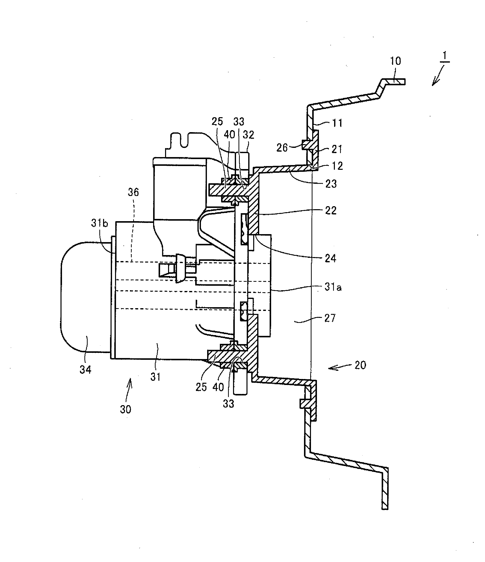
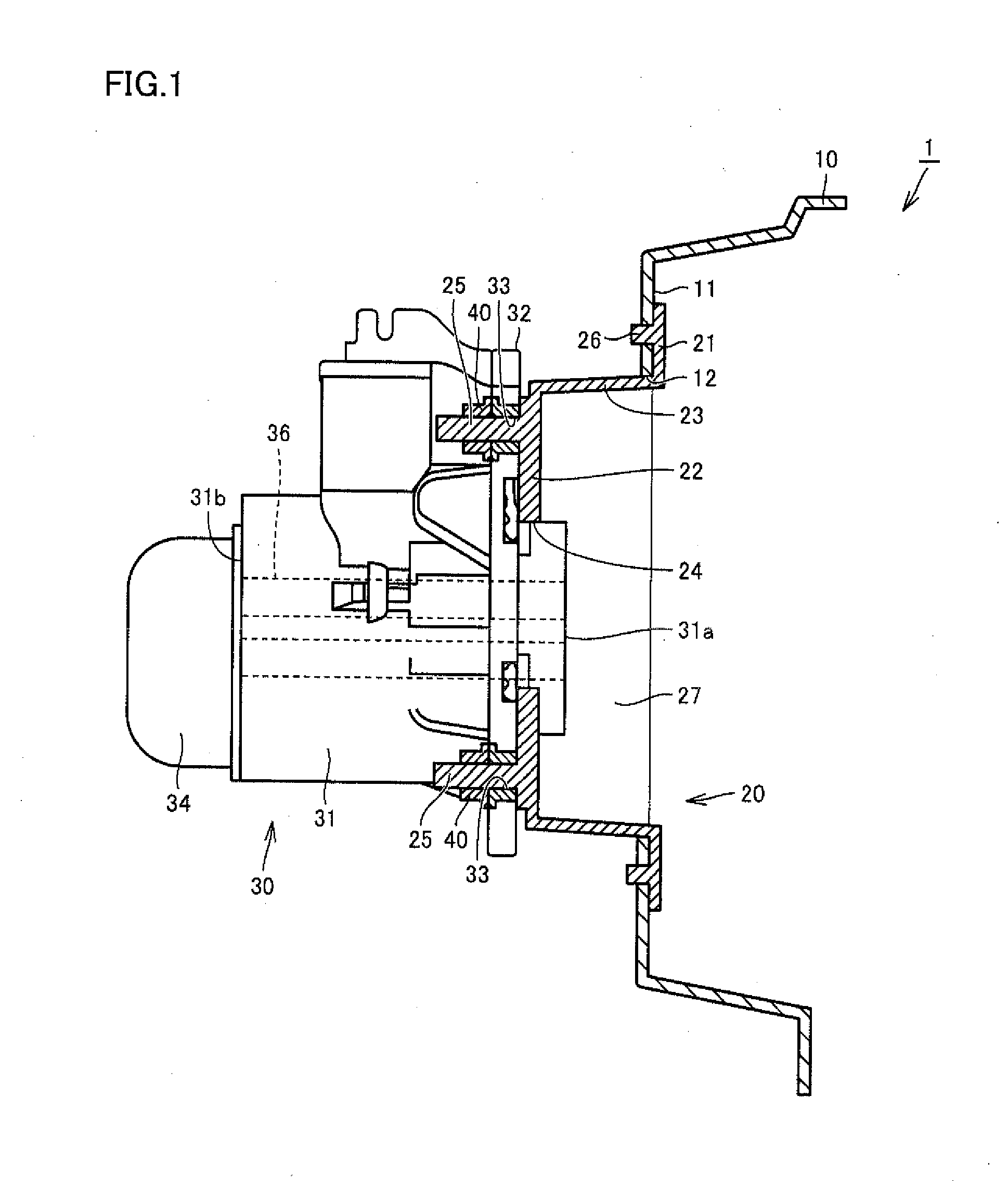
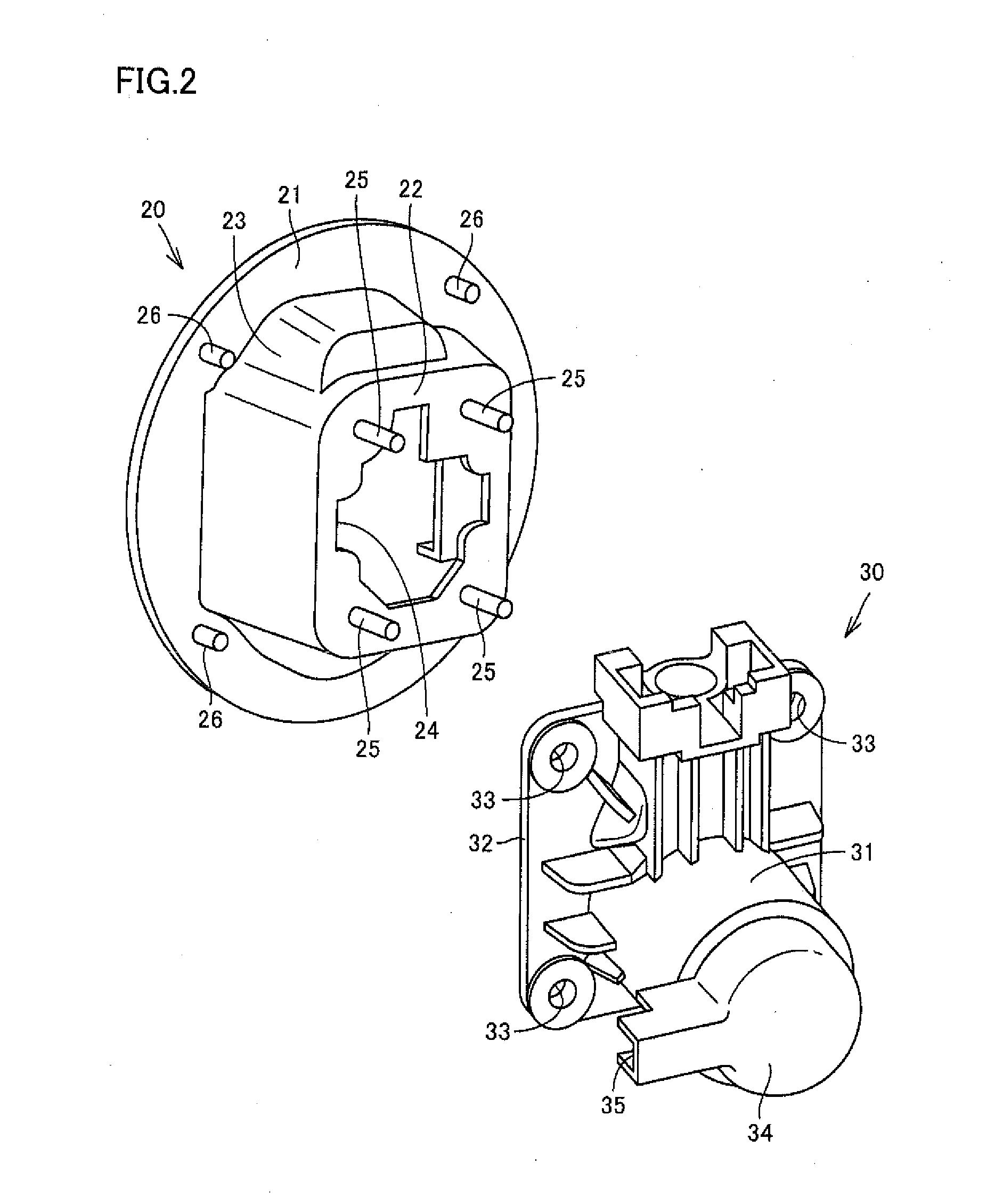
[0024]FIG. 1 is a cross-sectional view schematically showing a vehicle charging unit according to the present embodiment. FIG. 2 is an exploded perspective view of a lid box and an inlet that are included in the vehicle charging unit shown in FIG. 1. Referring to FIG. 1 and FIG. 2, a vehicle charging unit 1 according to the present embodiment will be described. The vehicle charging unit 1 is removably connected to a charging cable connected to an external power supply (not shown) for charging a power storage device (not shown) of a plug-in vehicle such as an EV or a PHV. AC (Alternating Current) power supplied through the vehicle charging unit 1 is converted into DC (Direct Current) power by a converter (not shown)...


PUM


Abstract

A vehicle charging unit includes a lid box inserted into a first hole in the body of a vehicle from outside of the vehicle and attached to the body, and an inlet fixed to the lid box. The lid box includes an attachment portion, a bottom having a second hole formed therein, and a sidewall. The bottom has a stud bolt protruding toward inside of the vehicle in a state in which the lid box is attached to the body. The inlet includes a barrel portion capable of receiving a charge connector from outside of the vehicle and a collar portion positioned around the barrel portion. The barrel portion is inserted into the second hole from inside of the vehicle and the collar portion is fixed with the stud bolt, whereby the inlet is fixed to the lid box.

Description

[0001]This nonprovisional application is based on Japanese Patent Application No. 2014-031980 filed on Feb. 21, 2014 with the Japan Patent Office, the entire contents of which are hereby incorporated by reference.BACKGROUND OF THE INVENTION[0002]1. Field of the Invention[0003]The present invention relates to a vehicle charging unit removably connected to a charging cable connected to an external power supply.[0004]2. Description of the Background Art[0005]In recent years, plug-in vehicles such as EVs (Electric Vehicles) and PHVs (Plug-in Hybrid Vehicles) have been developed, which include a system for charging a power storage device with power supplied from an external power supply such as a plug-in station. Such a plug-in vehicle has a charging unit on a side face of the vehicle to allow external charging through a charging cable.[0006]For example, Japanese Patent Laying-Open No. 2011-131772 discloses a charging unit including an inlet connectable with a charging cable, a guide for...

Claims


Application Information

Patent Timeline
IPC IPC(8): B60L11/18
CPCB60L11/1818B60L2210/30Y02T10/7072Y02T90/14B60L53/16Y02T10/70Y02T10/72Y02T90/12
Inventor SASAKI, MASARUYAMAZAKI, HIROYUKIKITANO, EIJI
Owner TOYOTA JIDOSHA KK
Learn More