
Dynamic polarization and coupling control from a steerable cylindrically fed holographic antenna

a cylindrically fed, dynamic technology, applied in the direction of linear waveguide fed arrays, individually energised antenna arrays, non-resonant long antennas, etc., can solve the problems of beam formation only at one static angle, polarization fidelity maintained during scanning is questionable, and beam performance is not good,

Active Publication Date: 2015-08-20
KYMETA
View PDF2 Cites 169 Cited by
  • Summary
  • Abstract
  • Description
  • Claims
  • Application Information

AI Technical Summary

Benefits of technology

The present invention architecture has better beam performance than linear feeds, which means it can produce better beam performance. This is achieved by the natural taper at the edges of the product.

Problems solved by technology

The primary limitations are scan range (Elevation between 20 and 70 degrees, no broadside possible) and beam performance (sometimes limiting to Rx only).
The limitation of the antennas described in both these papers is that the beam is formed only at one static angle.
While Sievenpiper has shown how a dynamic scanning antenna would be achieved, the polarization fidelity maintained during scanning is questionable.
Since these elements are fixed and cannot be rotated dynamically, there is no way to scan and maintain polarization control.
The most expensive class of options is a full phased-array antenna.
More recently, combining of mechanical movement in one axis with electronic scanning in an orthogonal axis has resulted in structures with a high aspect ratio that require less volume, but sacrifice beam performance or dynamic polarization control, such as Thinkom's system.
However, the waveguide designs have impedance swing near broadside (a band gap created by 1-wavelength periodic structures); require bonding with unlike CTEs; have an associated ohmic loss of the feed structure; and / or have thousands of vias to extend to the ground-plane.

Method used


Image

  • Dynamic polarization and coupling control from a steerable cylindrically fed holographic antenna
  • Dynamic polarization and coupling control from a steerable cylindrically fed holographic antenna
  • Dynamic polarization and coupling control from a steerable cylindrically fed holographic antenna

Examples


Embodiment Construction

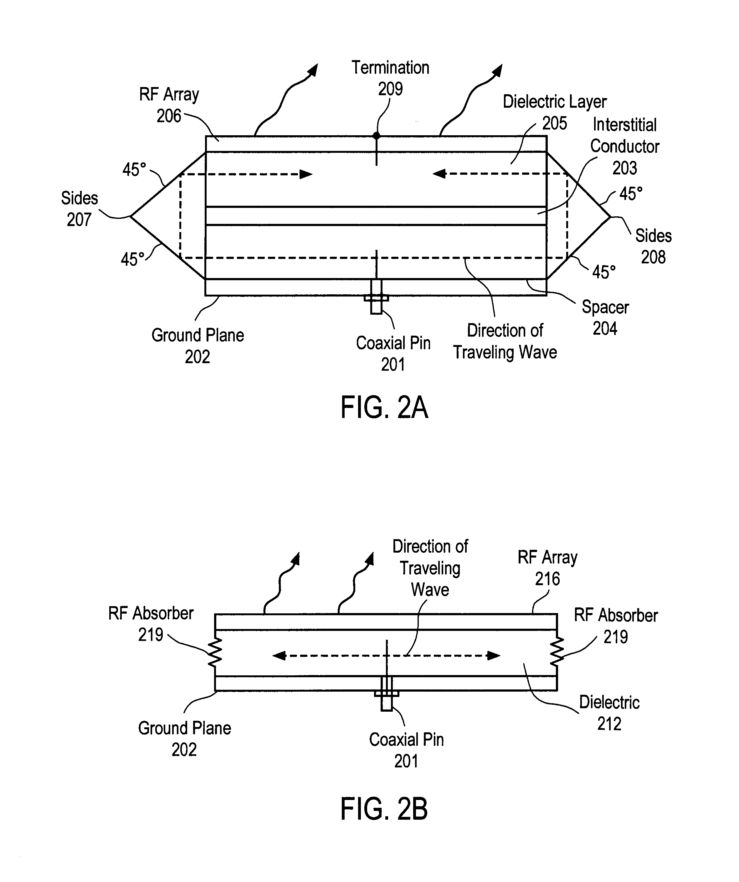
[0032]Embodiments of the invention include an antenna design architecture that feeds the antenna from a central point with an excitation (feed wave) that spreads in a cylindrical or concentric manner outward from the feed point. The antenna works by arranging multiple cylindrically fed subaperture antennas (e.g., patch antennas) with the feed wave. In an alternative embodiment, the antenna is fed from the perimeter inward, rather than from the center outward. This can be helpful because it counteracts the amplitude excitation decay caused by scattering energy from the aperture. Scattering occurs similarly in both orientations, but the natural taper caused by focusing of the energy in the feed wave as it travels from the perimeter inward counteracts the decreasing taper caused by the intended scattering.

[0033]Embodiments of the invention include a holographic antenna based on doubling the density typically required to achieve holography and filling the aperture with two types of orth...


PUM


Abstract

An apparatus is disclosed herein for a cylindrically fed antenna and method for using the same. In one embodiment, the antenna comprises an antenna feed to input a cylindrical feed wave and a tunable slotted array coupled to the antenna feed.

Description

PRIORITY[0001]The present patent application claims priority to and incorporates by reference the corresponding provisional patent application Ser. No. 61 / 941,801, titled, “Polarization and Coupling Control from a Cylindrically Fed Holographic Antenna” filed on Feb. 19, 2014, as well as corresponding provisional patent application Ser. No. 62 / 012,897, titled “A Metamaterial Antenna System for Communications Satellite Earth Stations, filed Jun. 16, 2014.FIELD OF THE INVENTION[0002]Embodiments of the present invention relate to the field of antennas; more particularly, embodiments of the present invention relate to an antenna that is cylindrically fed.BACKGROUND OF THE INVENTION[0003]Thinkom products achieve dual circular polarization at Ka-band using PCB-based approaches, generally using a Variable Inclined Transverse Stub, or “VICTS” approach with two types of mechanical rotation. The first type rotates one array relative to another, and the second type rotates both in azimuth. The ...

Claims


Application Information

Patent Timeline
Patent Type & Authority Applications(United States)
IPC IPC(8): H01Q3/24H01Q11/02H01Q21/00H01Q1/48
CPCH01Q3/247H01Q21/0031H01Q21/005H01Q3/28H01Q9/0442H01Q21/0012H01Q21/065H01Q21/20H01Q3/34H01Q13/106
Inventor BILY, ADAMKUNDTZ, NATHANJOHNSON, MIKALA
Owner KYMETA
Learn More