
Vehicle roof structure

a technology for roof panels and vehicles, applied in roofs, soldering devices, manufacturing tools, etc., can solve the problems of difficult joining of aluminum roof panels to steel body panels, inability to see the visible segment of roof panels, and inability to create compressive stresses in aluminum roof panels. , to achieve the effect of preventing galvanic corrosion, reducing thermal distortion of attached roof panels, and preventing galvanic corrosion

Inactive Publication Date: 2015-08-06
HONDA MOTOR CO LTD
View PDF2 Cites 17 Cited by
  • Summary
  • Abstract
  • Description
  • Claims
  • Application Information

AI Technical Summary

Benefits of technology

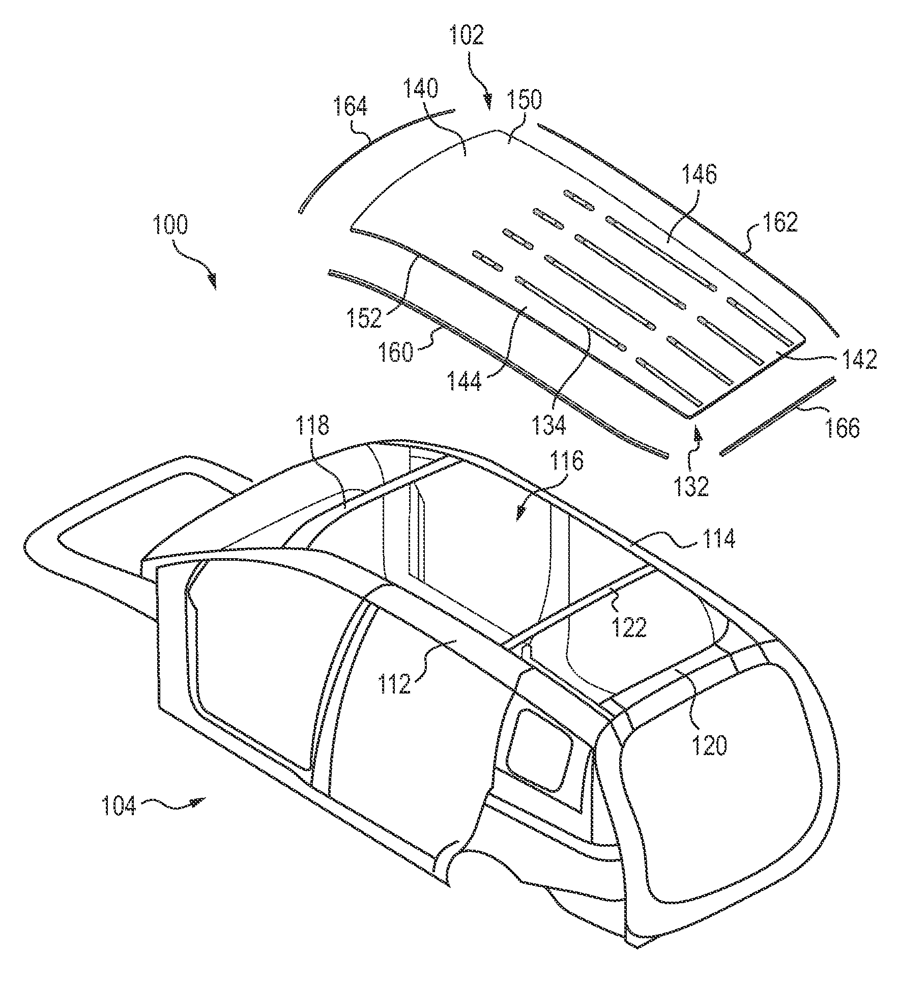
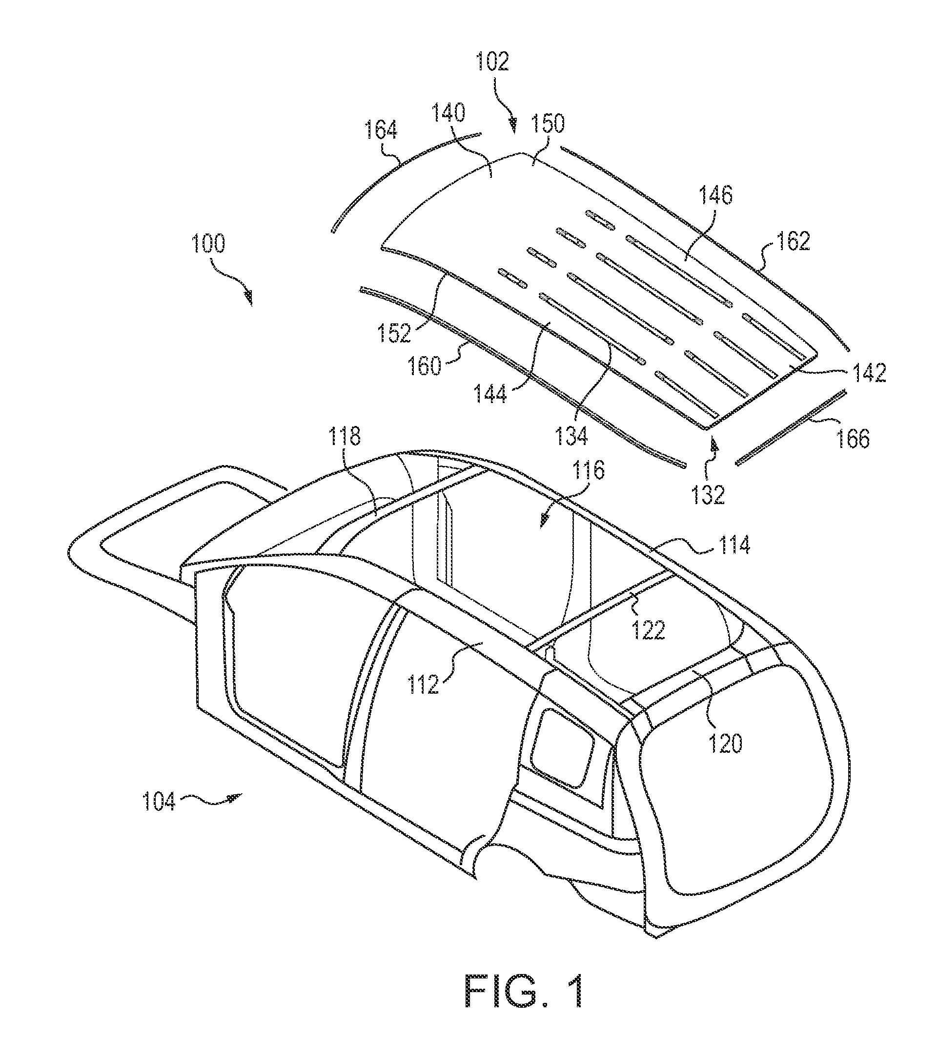
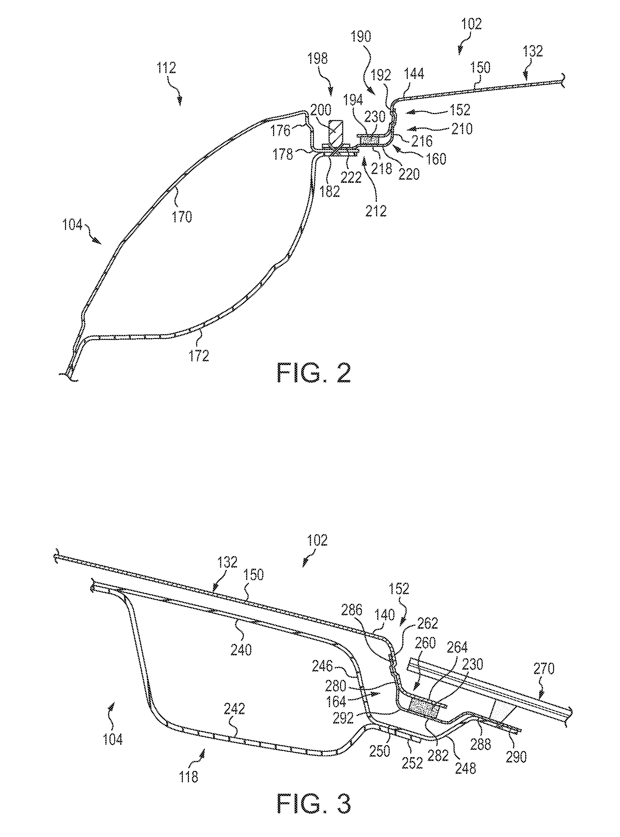
The patent describes a vehicle assembly with a roof structure and a vehicle body. The roof structure is made of aluminum or aluminum alloy and the vehicle body is made of steel or steel alloy. The roof panel is attached to the vehicle body using brackets that are made of steel or a steel alloy. An adhesive is used to bond the bracket to the vehicle body and to prevent corrosion between the dissimilar materials of the roof panel and bracket. This adhesive also reduces thermal distortion of the attached roof panel when the vehicle assembly is heated during manufacture. The roof structure is also supported by the vehicle body's side panels and roof rails. This design ensures a continuous and uniform vertical space between the roof panel and the vehicle body, which improves the overall stability and strength of the vehicle assembly.

Problems solved by technology

Joining an aluminum roof panel to a steel body panel is difficult due to the thermal expansion considerations of the dissimilar materials.
The combination of the aluminum roof panel attached to the steel body may create compressive stresses in the aluminum roof panel when the body is subjected to elevated temperatures such as those required to cure or bake the paint applied to the body.
These stresses may lead to unacceptable appearance features in the visible segment of the roof panel.
This approach, though appealing from a vehicle mass-reduction viewpoint, raises issues due to the significantly different coefficients of thermal expansion of aluminum and steel (about 22.5×10⁻⁶ m / m K for aluminum and about 13×10−6 m / m K for steel).
Further, because the steel and aluminum are permanently joined together by the rivets, this difference in thermal expansion of steel and aluminum will develop stresses in the aluminum and steel whenever the vehicle body temperature differs from the temperature at which the joint was made.
Since plastic deformation is not reversed on cooling, any such deformation may result in an appearance feature such as a crease or buckle in the roof panel which could be unacceptable to the customer.
Further, having the roof and vehicle body panels in contact or electrically connected can create galvanic corrosion.
The risk for this corrosion is increased when water is present, such as in the roof gutter areas.
However, the heat from the paint bake ovens can cause distortion of the aluminum roof panel relative to the steel body, creating a bowing effect.

Method used


Image

  • Vehicle roof structure
  • Vehicle roof structure
  • Vehicle roof structure

Examples


Embodiment Construction

[0013]It should be understood that the description and drawings herein are merely illustrative and that various modifications and changes can be made in the structures disclosed without departing from the present disclosure. In general, the figures of the exemplary vehicle roof structure are not to scale. As used herein, lateral directions are transverse across the vehicle, i.e., left and right directions. Likewise, longitudinal directions refer to forward and rearward directions of vehicle travel, and the vertical directions relate to elevation, i.e., upward and downward directions. It will also be appreciated that the various identified components of the exemplary vehicle roof structure disclosed herein are merely terms of art that may vary from one manufacturer to another and should not be deemed to limit the present disclosure.

[0014]Increasingly, low-carbon steel or steel alloys, long the material of choice for vehicle body construction, is being displaced by higher strength-to-...


PUM

PropertyMeasurementUnit
temperatureaaaaaaaaaa
temperaturesaaaaaaaaaa
perimeteraaaaaaaaaa

Abstract

A vehicle assembly includes a roof structure having a roof panel formed of aluminum or an aluminum-based alloy and a vehicle body formed of steel or a steel alloy supporting the roof structure. The vehicle body includes a pair of laterally spaced side panels, a front roof rail and a rear roof rail. A bracket formed of steel or a steel alloy secures the roof structure to the vehicle body. The bracket has a first portion fastened to the roof panel and a second portion extending away from the roof structure and welded to the vehicle body. An adhesive located inward of the connection of the vehicle body and second portion of the bracket bonds the second portion to the vehicle body. The adhesive seals the connection of the roof panel and bracket first portion and reduces thermal distortion of the attached roof panel relative to the vehicle body.

Description

BACKGROUND[0001]The substitution of aluminum or aluminum-based alloy roof panels for the low-carbon steel or steel alloy roof panels most commonly used in motor vehicles is an attractive option for vehicle mass reduction. Often, however, the remainder of the vehicle body structure continues to be fabricated of steel. Joining an aluminum roof panel to a steel body panel is difficult due to the thermal expansion considerations of the dissimilar materials. The combination of the aluminum roof panel attached to the steel body may create compressive stresses in the aluminum roof panel when the body is subjected to elevated temperatures such as those required to cure or bake the paint applied to the body. These stresses may lead to unacceptable appearance features in the visible segment of the roof panel.[0002]Manufacturers currently secure the aluminum roof panel to the steel body panel after the weld process in assembly. This process typically includes an adhesive bonding operation. Sel...

Claims


Application Information

Patent Timeline
Patent Type & Authority Applications(United States)
IPC IPC(8): B62D27/02B23K31/02
CPCB62D27/04B62D25/06B62D29/008
Inventor HINZ, CHRISTOPHERISHIKAWA, MASAHIRO
Owner HONDA MOTOR CO LTD
Learn More