
Fishing reel

a reel and reel body technology, applied in the field of fishing reels, can solve the problems of affecting the operation of the reel, the spool shaft and the inner peripheral surface burnout, and the spool shaft burnout, so as to reduce frictional resistance, reduce relative position errors, and enhance the abrasion resistance of the spool shaft

Active Publication Date: 2012-09-06
SHIMANO INC
View PDF8 Cites 8 Cited by
  • Summary
  • Abstract
  • Description
  • Claims
  • Application Information

AI Technical Summary

Benefits of technology

[0012]It is an advantage of the present invention to enhance abrasion resistance of the spool shaft and reduce frictional resistance between the outer peripheral surface of the spool shaft and the inner peripheral surface of the bearing or the pinion gear.
[0013]It is another advantage of the present invention to reduce a relative positional error between a spool and a spool shaft in fishing components as much as possible, reduce manufacturing cost, and prevent galvanic corrosion of a component made of magnesium alloy.SUMMARY
[0014]A fishing reel for winding and releasing a fishing line is provided. The fishing reel includes a tubular spool being configured to wind the fishing line onto an outer periphery thereof, a spool shaft made of metal, the spool shaft being attached to an inner periphery of the spool, and a Diamond Like Carbon (DLC) layer being formed on a surface layer side of the spool shaft.

Problems solved by technology

However, the magnesium-alloy components can have the following drawbacks when other components made of metal (e.g., stainless alloy) are disposed closer to the magnesium-alloy components.
For example, galvanic corrosion can be caused in the magnesium-alloy components when conductive liquid (e.g., salty water) intrudes into an area between the other metal components and the magnesium-alloy components.
Such relative rotation with a high load or at a high speed can result in burnout between the outer peripheral surface of the spool shaft and the inner peripheral surface of the bearing or the pinion gear.
However, oil or grease can flow out due to intrusion of sea water or due to washing by water after use.
In addition, manufacturing cost can be thereby increased.
Therefore, a relative positional error is easily produced between the spool and the spool shaft.
This can result in run-out of the outer periphery of the spool with respect to the spool shaft.

Method used


Image

  • Fishing reel
  • Fishing reel
  • Fishing reel

Examples


Embodiment Construction

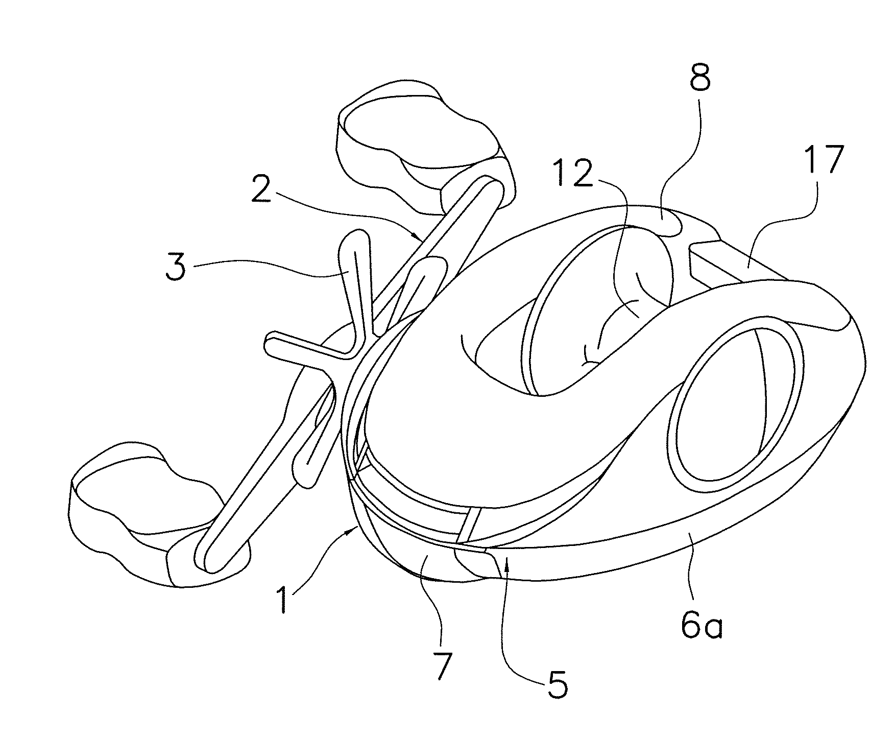
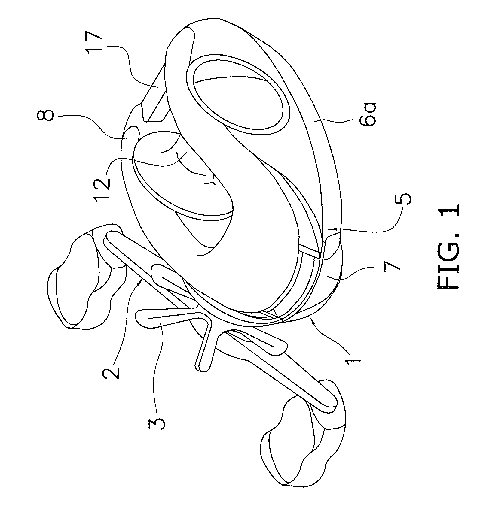
[0026]As illustrated in FIG. 1, a fishing reel according to an exemplary embodiment of the present invention is a low profile dual-bearing reel for bait-casting. The dual-bearing reel includes a reel unit 1, a handle 2 for spool rotation, and a star drag 3 for drag regulation. The handle 2 is disposed lateral to the reel unit 1. The star drag 3 is disposed on the reel unit side of the handle 2.

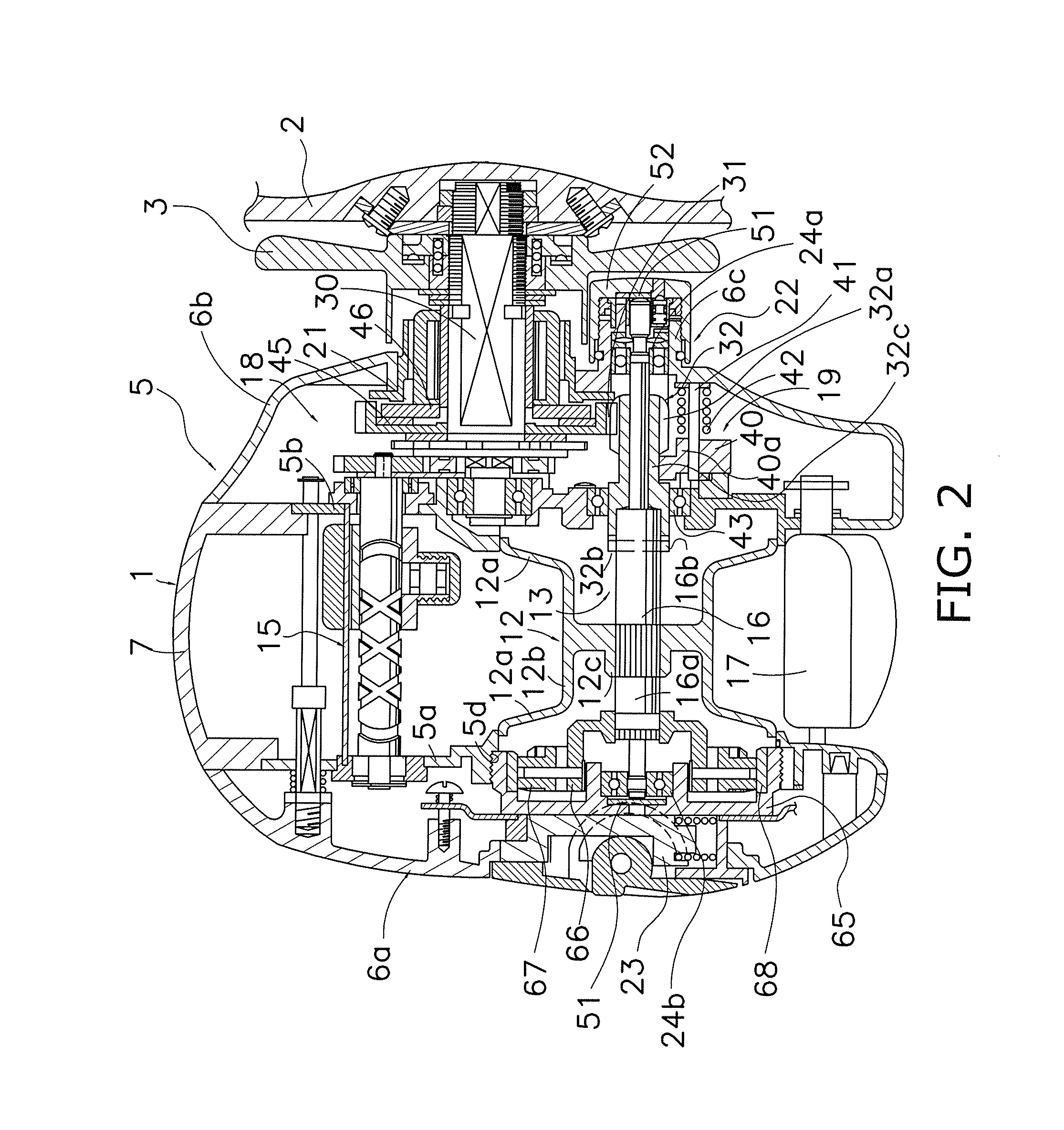
[0027]As illustrated in FIG. 2, the reel unit 1 includes a frame 5 and a pair of first and second side covers 6a and 6b attached to the both lateral sides of the frame 5. As illustrated in FIG. 1, the reel unit 1 further includes a front cover 7 and a thumb rest 8. The front cover 7 covers the front of the reel unit 1, whereas the thumb rest 8 covers the top of the reel unit 1. Further, a spool 12 for winding a fishing line is attached to the inside of the reel unit 1 in a rotatable and detachable state.

[0028]The frame 5 includes a pair of first and second side plates 5a and 5b and a plurality...


PUM


Abstract

A fishing reel for winding and releasing a fishing line includes a tubular spool being configured to wind the fishing line onto an outer periphery thereof, a spool shaft made of metal, the spool shaft being attached to an inner periphery of the spool, and a Diamond Like Carbon (DLC) layer being formed on a surface layer side of the spool shaft.

Description

CROSS-REFERENCE TO RELATED APPLICATIONS[0001]This application claims priority to Japanese Patent Application Nos. 2011-047114 filed on Mar. 4, 2011 and 2011-133243 filed on Jun. 15, 2011, the entirety of which is hereby incorporated by reference.BACKGROUND OF THE INVENTION[0002]1. Field of the Invention[0003]The present invention relates to a fishing reel, particularly to a fishing reel for winding and releasing a fishing line.[0004]2. Background Art[0005]Some fishing reels are configured to wind and release a fishing line while being attached to a fishing rod. Such fishing reels are mainly classified into the spinning reels and the dual-bearing reels. A fishing reel of the both types generally includes a reel unit, a spool shaft, and a spool. The reel unit is attached to the fishing rod. The spool shaft is supported by the reel unit. The spool is attached to the spool shaft for winding the fishing line. More specifically, a dual-bearing reel has a structure in which the spool is ro...

Claims


Application Information

Patent Timeline
IPC IPC(8): A01K89/00
CPCA01K89/015A01K89/01912A01K89/01931A01K89/01
Inventor NIITSUMA, AKIRANAKAGAWA, SHOUJIIKEBUKURO, SATOSHIKAWASAKI, KEN'ICHI
Owner SHIMANO INC
Learn More