Printed board and image forming apparatus

a technology of image forming apparatus and printed board, which is applied in the direction of instrumentation, electrographic process, inspection/indentification of circuits, etc., can solve the problems of poor assembly, unstable contact state, and high voltage cable supply costs, so as to reduce the area required, reduce the force, and facilitate the effect of visual inspection of the contact portion

Active Publication Date: 2015-07-30
CANON KK
View PDF5 Cites 10 Cited by
  • Summary
  • Abstract
  • Description
  • Claims
  • Application Information

AI Technical Summary

Benefits of technology

[0008]The present invention has been made in view of the above described circumstances, and enables a reduction in an area required for a contact portion, a decrease in a force that is necessary at the time of assembly, as well as easy performance of a visual check of a contact portion.

Problems solved by technology

In a case where the power supply board and the main body of the image forming apparatus are connected using a high voltage cable in order to apply a high voltage generated by the power supply board to the charge device, the developing device and the transfer device, the assemblability is poor and costs are incurred in providing the high voltage cable.
Consequently, when pushing the printed board against the spring member and fixing the printed board in that state, the contact state is unstable, and there is a high possibility that the spring member will be deformed.
Therefore, the diameter of the coil portion cannot be easily reduced.
Consequently, there is the problem that the proportion of the area occupied by the contact point with respect to the overall power supply board increases, and this leads to an increase in the substrate area.
When installing the power supply board in the main body of the image forming apparatus, the power supply board directly receives a repulsive force of the spring member, and because the amount of force required when installing the power supply board increases as the number of contact portions increases, there is the problem that the assembly workability is poor.
In addition, there is also the problem that, depending on the size and quality of the material of the power supply board as well as the number of contact points, the power supply board itself may be bent by the repulsive force of the spring member, and stress may be applied to components that are mounted on the power supply board by such bending.
However, there is also a problem that it is not possible to visually check whether a contact portion of the power supply board and a coil of the spring member securely contact each other.

Method used


Image

  • Printed board and image forming apparatus
  • Printed board and image forming apparatus
  • Printed board and image forming apparatus

Examples


embodiment 1

Configuration of Image Forming Apparatus

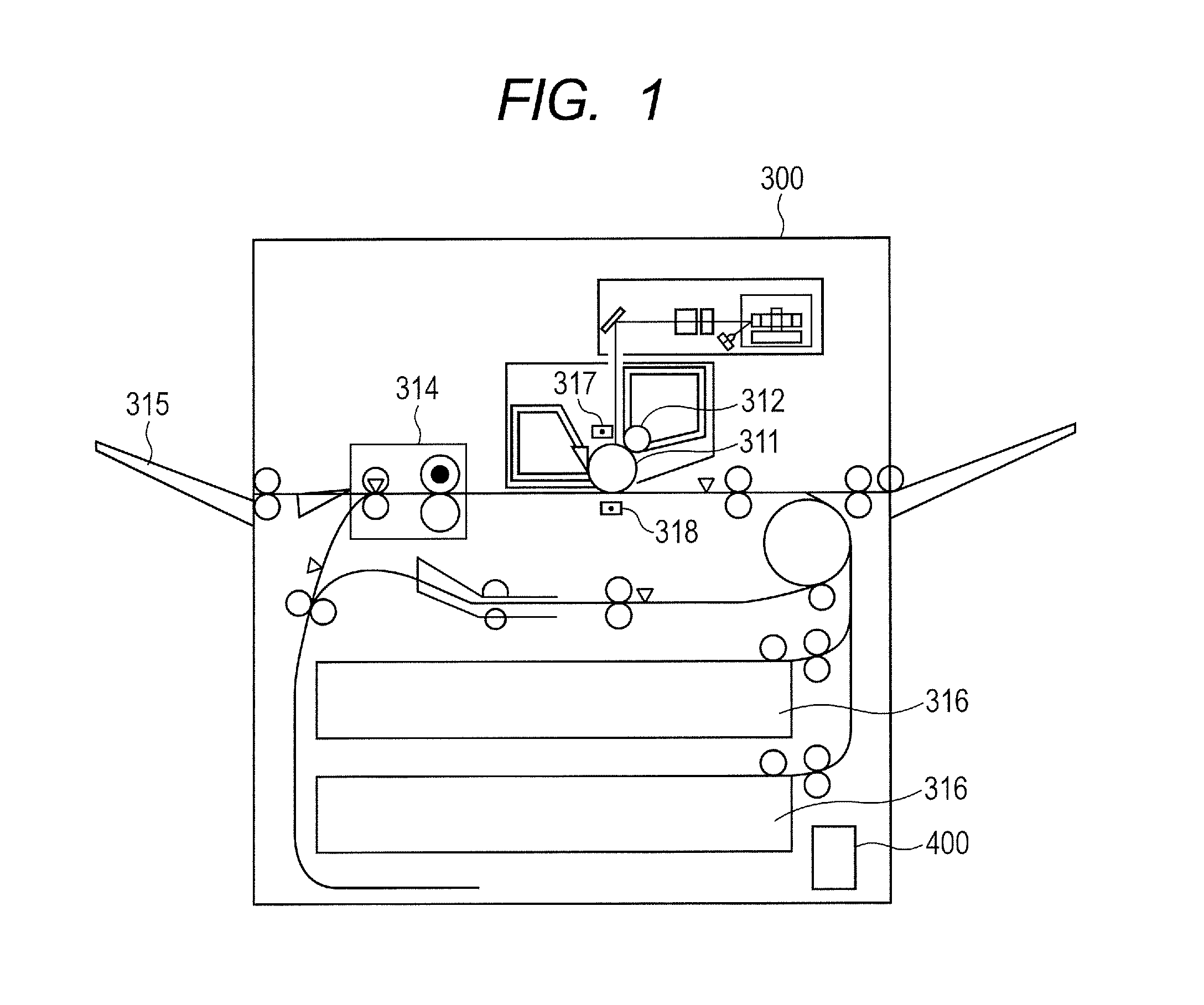
[0023]A laser beam printer is described hereunder as one example of an image forming apparatus according to Embodiment 1. FIG. 1 illustrates the schematic configuration of a laser beam printer that is one example of a printer adopting an electrophotographic system. A laser beam printer 300 includes a photosensitive member 311 that is an image bearing member on which an electrostatic latent image is formed, a charge device 317 (charge unit) that charges the photosensitive member 311 to a predetermined potential, and a developing device 312 (developing unit) that develops an electrostatic latent image formed on the photosensitive member 311 with toner. A toner image that was developed on the photosensitive member 311 is then transferred by a transfer device 318 (transfer unit) onto a sheet (not illustrated in the drawings) as a recording material that is supplied from a cassette 316, the toner image that was transferred onto the sheet is fixed b...

embodiment 2

[0043]In Embodiment 1, an embodiment was described in which a slit that is a through hole is provided in the inner part of a printed board. In Embodiment 2, an embodiment will be described in which a slit is provided at an edge of the printed board.

[0044][Configuration of Contact Portion]

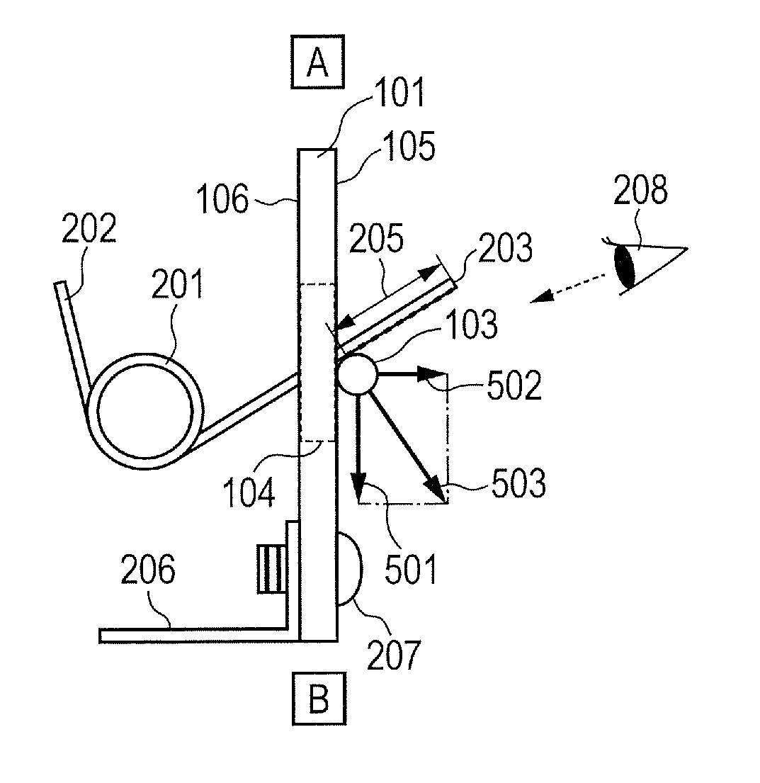
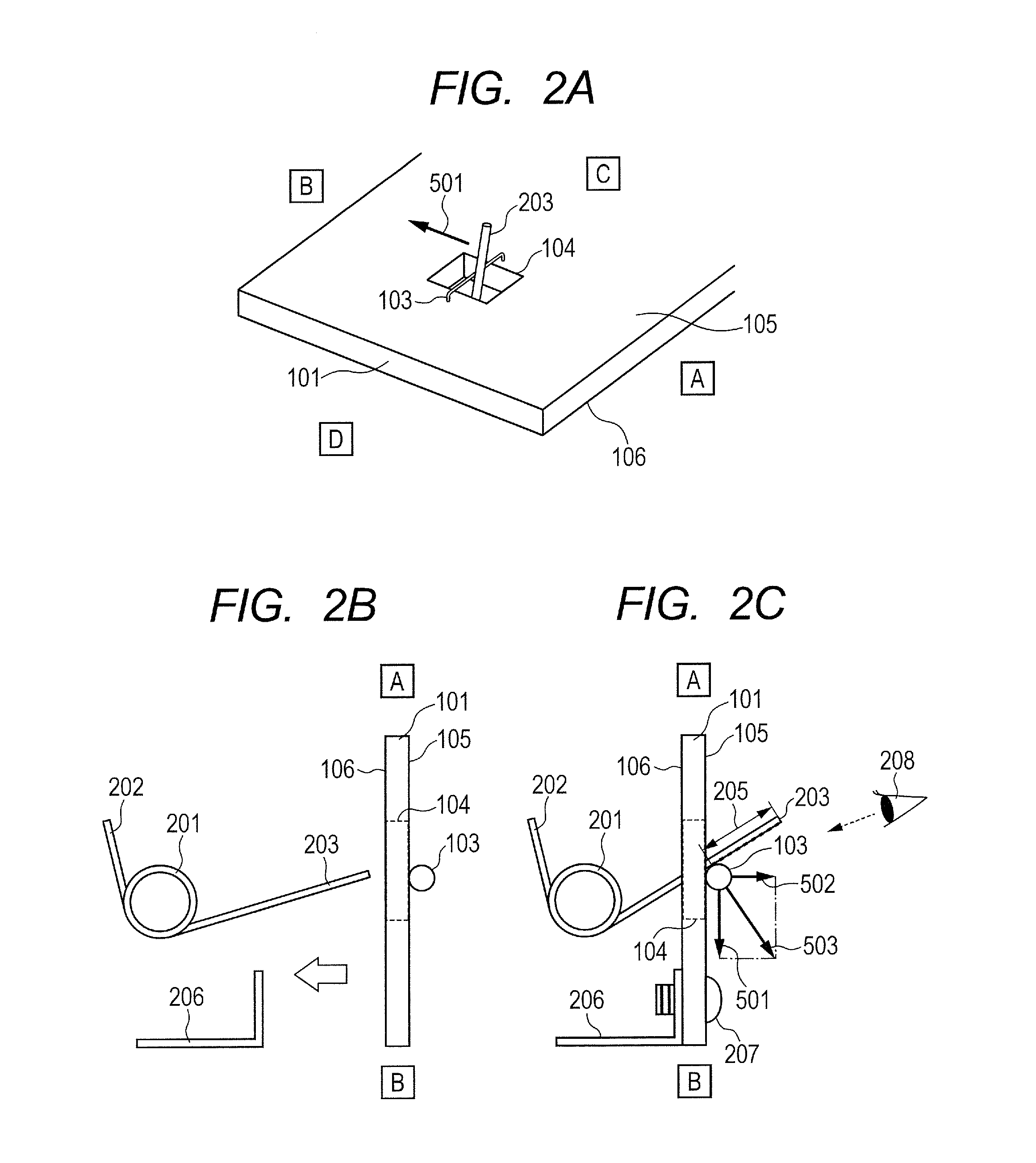
[0045]FIG. 3A is a perspective view illustrating a contact portion between the jumper wire 103 that is provided in the printed board 101 and the arm portion 203 on the printed board 101 side of the torsion coil spring. In FIG. 3A, components that are the same as in FIG. 2A of Embodiment 1 are denoted by the same reference symbols. Hereunder, a difference with respect to the configuration illustrated in FIG. 2A of Embodiment 1 will be described, and a description of the same configuration as in FIG. 2A is omitted.

[0046]The difference between the configuration illustrated in FIG. 3A of the present embodiment and the configuration illustrated in FIG. 2A of Embodiment 1 is as follows. That is, in FIG. 2...

embodiment 3

[0050]In Embodiments 1 and 2, embodiments were described of a case in which a single contact portion is provided in the printed board. According to Embodiment 3, an embodiment is described of a case where two contact portions are provided in the printed board.

[0051][Configuration of Contact Portion]

[0052]FIG. 4A is a perspective view illustrating contact portions between jumper wires 103a and 103b provided on the printed board 101 and arm portions 203a and 203b on the printed board 101 side of torsion coil springs. Although the configuration illustrated in FIG. 4A is similar to the configuration illustrated in Embodiment 2, the present embodiment differs from Embodiment 2 in the respect that two contact portions are provided in the present embodiment in contrast to the single contact portion provided in Embodiment 2. FIG. 4B is a side view illustrating a contact portion at which the arm portion 203a of a torsion coil spring contacts the jumper wire 103a, and the printed board 101. I...


PUM


Abstract

The printed board includes a slit portion and a first conductive member that is provided straddling the slit portion. In a state in which the printed board is attached to an apparatus to which one end of a second conductive member having an elastic force is connected, another end of the second conductive member contacts the first conductive member, and the another end of the second conductive member passes through the slit portion.

Description

BACKGROUND OF THE INVENTION[0001]1. Field of the Invention[0002]The present invention relates to a printed board and an image forming apparatus that is equipped with the printed board.[0003]2. Description of the Related Art[0004]An image forming apparatus such as a laser beam printer includes a charge device, a developing device, a transfer device and a fixing device. The charge device charges the surface of a photosensitive member to a uniform charge. The developing device develops a latent image that is formed on the photosensitive member by a laser beam or the like with toner. The transfer device transfers the developed toner image on the photosensitive member onto a transfer material. In addition, the fixing device includes a heater that is driven by an alternating current power supply, and heats the toner image that was transferred onto the transfer material to thereby fix the toner image on the transfer material.[0005]A high voltage of several hundred volts to several kilovolt...

Claims


Application Information

Patent Timeline
Patent Type & Authority Applications(United States)
IPC IPC(8): G03G15/00H05K1/00
CPCH05K1/0269H05K2201/20G03G15/50H05K1/0296H05K1/117H05K3/403H05K3/4015H05K2201/0394H05K2201/09063H05K2201/09181H05K2201/10363H05K2201/10287G03G15/80G03G21/1652
Inventor SERIZAWA, SHINSUKE
Owner CANON KK
Why Eureka
Try Eureka