
Super-resolution microscopy method and device

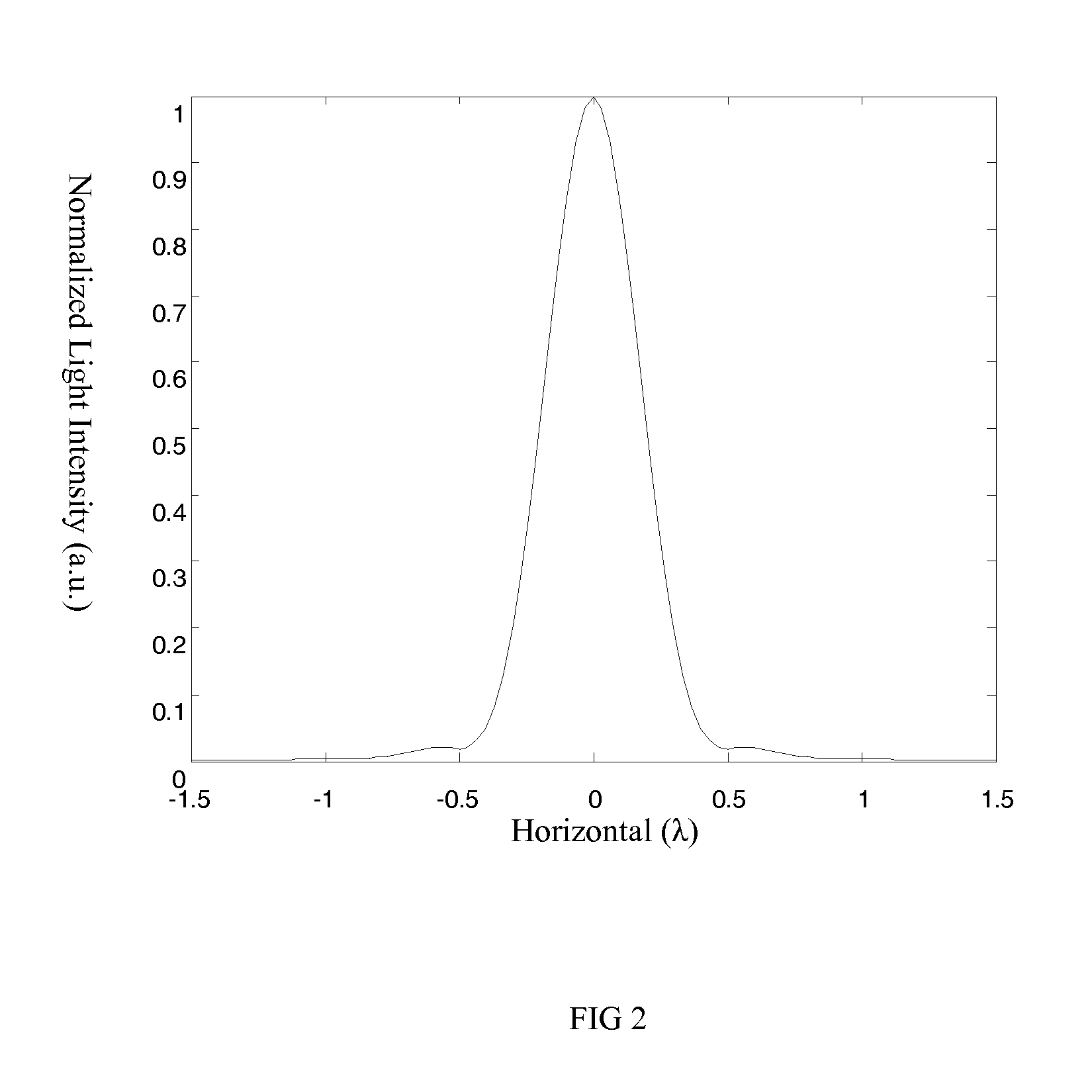
a microscopy and super-resolution technology, applied in the field of super-resolution, can solve the problems of limiting the resolution of conventional far-field optical microscopes to about half wave length, affecting the operation efficiency of the sted microscopy system, and affecting the operation efficiency of the sted microscope, so as to achieve the effect of simple structure and easy operation

Active Publication Date: 2015-07-30
ZHEJIANG UNIV
View PDF4 Cites 18 Cited by
  • Summary
  • Abstract
  • Description
  • Claims
  • Application Information

AI Technical Summary

Benefits of technology

The present invention has the advantage of being able to achieve higher resolution than previous techniques, even with lower light power. Additionally, the invention allows for quick image formation, with a frame frequency of up to 15 frames per second when scanning at 512×521 for each image.

Problems solved by technology

Due to the impact from diffraction of optical system, resolution obtained from conventional far-field microcopy method is limited.
Therefore, limiting resolution of conventional far-field optical microscope is normally restricted to about half wave length.
Despite of the fact that they all can achieve fluorescent super-resolution microscopy at the far field and obtain corresponding applications during practical tests, aforesaid several methods still have their own disadvantages.
Furthermore, STED microscopy system is relatively complicated, which is normally expensive.
Despite of the fact that SIM microscopy has lower requirements for light power, it still requires raster scanning, which may result in relatively slower image formation and complicated image forming system.
Image formation speed of STORM microscopy is also very slow, which is unlikely to be applied to real-time test of living cell at present.

Method used


Image

  • Super-resolution microscopy method and device
  • Super-resolution microscopy method and device
  • Super-resolution microscopy method and device

Examples


Embodiment Construction

[0065]The present invention is described in detail as follows in combination with embodiments and drawings; however, the present invention is not limited to this scope.

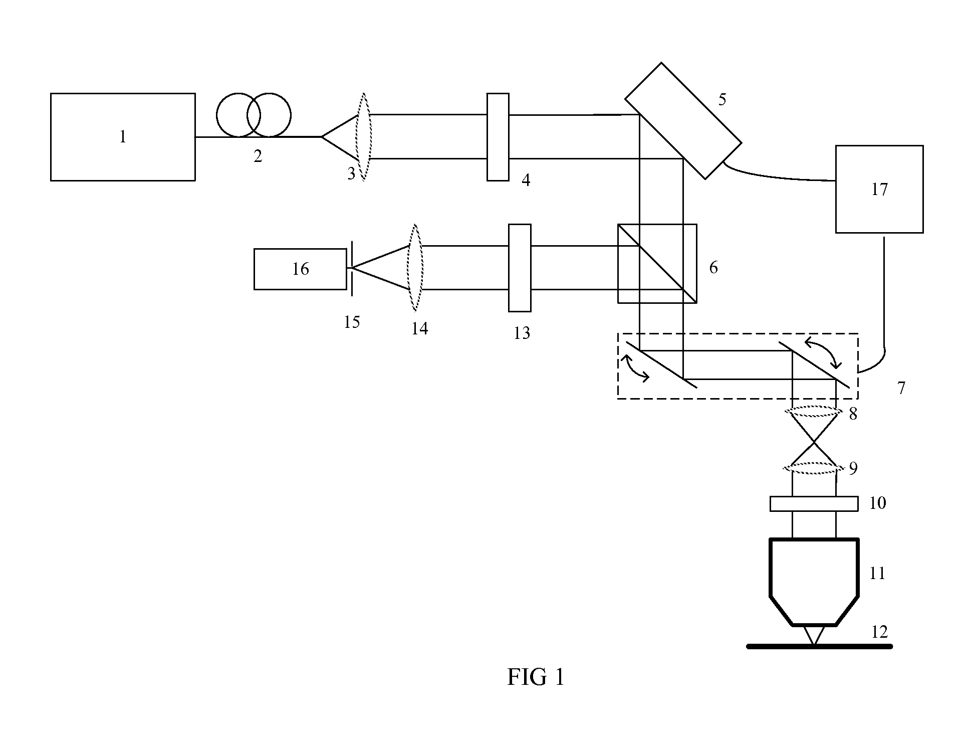
[0066]As shown in FIG. 1, a super-resolution device comprising a laser 1, a single-mode optical fiber 2, a collimation lens 3, a polarizer 4, a spatial light modulator 5, a beam splitter 6, a scanning galvanometer system 7, a scanning lens 8, a field lens 9, a ¼ wave plate 10, a microscope 11, a sample table 12, a band filter 13, a focusing lens 14, a pinhole 15, a detector 16 and a controller 17.

[0067]Wherein, the single-mode optical fiber 2, the collimation lens 3, the polarizer 4 and the spatial light modulator 5 are located on the optical axis of outgoing beam of the laser 1 in proper sequence; transparent axis of the polarizer 4 is parallel to the horizontal orientation.

[0068]Wherein, the beam splitter 6 and the scanning galvanometer system 7 are located on the optical axis of the beam modulated by the spatial li...


PUM

PropertyMeasurementUnit
super-resolution microscopyaaaaaaaaaa
distanceaaaaaaaaaa
angleaaaaaaaaaa

Abstract

This invention discloses a super-resolution microscopy method and device, of which the method comprises the following steps: converting laser beam into linearly polarized light after collimation; linearly polarized light is deflected and phase modulated by a spatial light modulator; the deflected beam is focused, collimated and then converted into circularly polarized light for projection on the sample to collect signal light from various scanning points on the sample, and obtaining the first signal light intensity; switching over modulation function to project linearly polarized light modulated by the second phase modulation on the sample to collect signal light from various scanning points on the sample, and obtaining the second signal light intensity; calculating valid signal light intensity to obtain the super-resolution image. This device features in a simple structure and easy operation, which can obtain a super-resolution beyond diffraction limit at a lower luminous power; it is quick in image formation with the frame frequency over 15 frames when the number of scanning points in each image is 512×512 .

Description

FIELD OF THE INVENTION [0001]The present invention is related to the super-resolution field, in particular to a super-resolution method and device that can achieve super-resolution beyond diffraction limit at the far field.BACKGROUND OF THE INVENTION[0002]Due to the impact from diffraction of optical system, resolution obtained from conventional far-field microcopy method is limited. According to Abbe's diffraction limit theory, dimension of the light spot formed through focusing of the light beam by the microscope is indicated asΔr=λ2NAby using the full width at half maximum; wherein, λ refers to the working wave length of the microscope; NA refers to the numerical aperture of the microscope used. Therefore, limiting resolution of conventional far-field optical microscope is normally restricted to about half wave length.[0003]In recent years, scientific researchers have proposed numerous super-resolution microscopy methods in an attempt to break through restrictions of optical diff...

Claims


Application Information

Patent Timeline
Patent Type & Authority Applications(United States)
IPC IPC(8): G01N21/27G02B21/00G01N21/25
CPCG01N21/27G01N21/255G01N2201/064G01N2201/06113G02B21/002G02B21/0032G02B21/0068G01N21/6458G02B27/58
Inventor KUANG, CUIFANGLI, SHUAIHAO, XIANGGU, ZHAOTAILIU, XU
Owner ZHEJIANG UNIV
Learn More