Sensor having multiple magnetic blocks of unevenly distributed magnetic fluxes in housing

Inactive Publication Date: 2015-07-30
CHENGDU KUANHE TECH +3
View PDF1 Cites 4 Cited by
  • Summary
  • Abstract
  • Description
  • Claims
  • Application Information

AI Technical Summary

Benefits of technology

The present invention is a power assistance bicycle sensor that has the following technical effects: a simple structure, a low cost, no signal blind area, and a high accuracy in motor control and power assistance for the rider. The sensor uses a Hall element to sense the movement of permanent magnetic blocks on a rotating disk, and the output signals of the Hall element are utilized to control the motor of the bicycle. The sensor is adaptable for power assistance bicycles and can provide precise position and speed information for the rider. The sensor is also adaptable for power assistance bicycles with a larger number of permanent magnetic blocks and can provide more accurate power assistance and motor control. The sensor is easy to use and comfortable for the rider.

Problems solved by technology

After a long time utilization, changes of spring constants of the flexible assembly lead to changes of control effects of the sensing signal and the controlled motor, so that the control effects can not meet the requirements of people's assistance.
In addition, the flexible assembly has a complicated structure and a high cost.
The flexible assembly utilized is not durable.
After a time of utilization, changes of spring constant of the flexible assembly lead to control effect changes of the controlled motor, so that the control effects can not meet the requirements of people's assistance.
In addition, the flexible assembly has a complicated structure and a high cost.
However, according to the patent application 01201843.0, each disc groups are the same, which cannot represent special power assistance requirements of the pedal on different positions.
That is to say, the output signal of the Hall element can not represent the power assistance requirements of the pedals at different positions, in such a manner that the power assistance requirement does not match the power assistance time, namely unsatisfactory man-machine coordination.
The sinusoidal wave outputted allow a disc group edge distance of not less than 4 cm, and preferably 5 cm, which causes a result that the number of the magnetic sheet groups are too few and that the man-machine cooperation is not satisfying.
In other words, when the technical solution of the patent application of 01201843.0 is utilized in a power-assist bicycle, the number of the magnetic sheet groups is limited to 8, the number of the control signal is too few and the man-machine cooperation is not satisfying.
The signal does not have a control function and is not capable of controlling the motor, so that when the assist power is particularly required, the power-assist function is lost.
The blind zone of the signal has a blind angle of 45 degrees, and the assist power can not be obtained when required in starting.
And the result is that the motor of the power-assist bicycle is not capable of providing assist power while requiring the assist power most.
In summary, except that the flexible assembly is not durable and has complicated structures, the diameter of the wheel is within 20 cm, which limits the number of the magnetic sheet group to 8.
The assist power can not meet the requirements.
The cyclist is not comfortable while riding.
Since one Hall element is not capable of representing the motion positions in one rotating circle of the pedal at different times, utilizing only one Hall element is not desirable.
However, utilizing multiple Hall elements has disadvantages as follows.
The disadvantage is that the permanent magnet itself is not capable of representing the rotating position of the pedal, and the rotating position of the pedal can only be represented by the positions of the multiple Hall elements provided on different corner positions.
Thus, utilizing only one Hall element is infeasible, and multiple Hall elements must be utilized.
As utilizing one Hall element is infeasible, utilizing three Hall elements inevitably leads to original segment errors of three control signals, which causes distortion of the required power assist model, so that the output of the assist power is not in accordance with the requirements of the assist power.
Particularly, due to variations of the environment temperatures, the sensor parameters of the three Hall elements may have great differences, which cause an result that different Hall elements output different voltages under the same power assist requirements.
Similarly, when identical assist power is required, different Hall elements may output an identical voltage, so that the motor generates only one identical assist power to output, which also brings the problem of inconformity between the outputs and the requirements of the assist power.
The integrated control signal is easy to generate a signal drift, so that the integrated control signal does not match with the motor controller and that the the power assist model is distorted.
Thus the integrated control signal as a whole generates the segment signal drift, i.e. the assist power model is distorted, which causes a result that no matter the motor controller selects any one of the three control signal for serving as a reference, the problems of inconformity between the requirements and the outputs of the assist power.
The number of the sensing sites is too few, so that the operation of the motor is unstable and the rider feels uncomfortable.
Thus, the power assist bicycle provided by the patent application is a power assist bicycle that makes the rider feels uncomfortable.
The blind zone of the signal has a blind angle of 45 degrees, and the assist power can not be obtained when required in starting.
And the result is that the motor of the power-assist bicycle is not capable of providing assist power while requiring the assist power most.
Both of the situations cause distortion of the assist power required model, i.e., the identical power assist requirements at different times obtains different power assist effects.
The more is the number of the Hall elements, the more serious is the distortion degree of the power assist required model, which limits the number of the Hall elements.
The few amounts of the Hall elements cause a result that the operation of the motor is not steady, the rider feels uncomfortable, and that the assist power is not available when starting.
Thus, the patent application by Naikang Wang always attends to one thing and loses sight of another between the distortionless of the power assist requirement model and the steady operation of the motor, and it is not possible to have both ways.

Method used


Image

  • Sensor having multiple magnetic blocks of unevenly distributed magnetic fluxes in housing
  • Sensor having multiple magnetic blocks of unevenly distributed magnetic fluxes in housing
  • Sensor having multiple magnetic blocks of unevenly distributed magnetic fluxes in housing

Examples


example 1

A Sensor Having Multiple Magnetic Blocks of Unevenly Distributed Magnetic Fluxes in a Housing

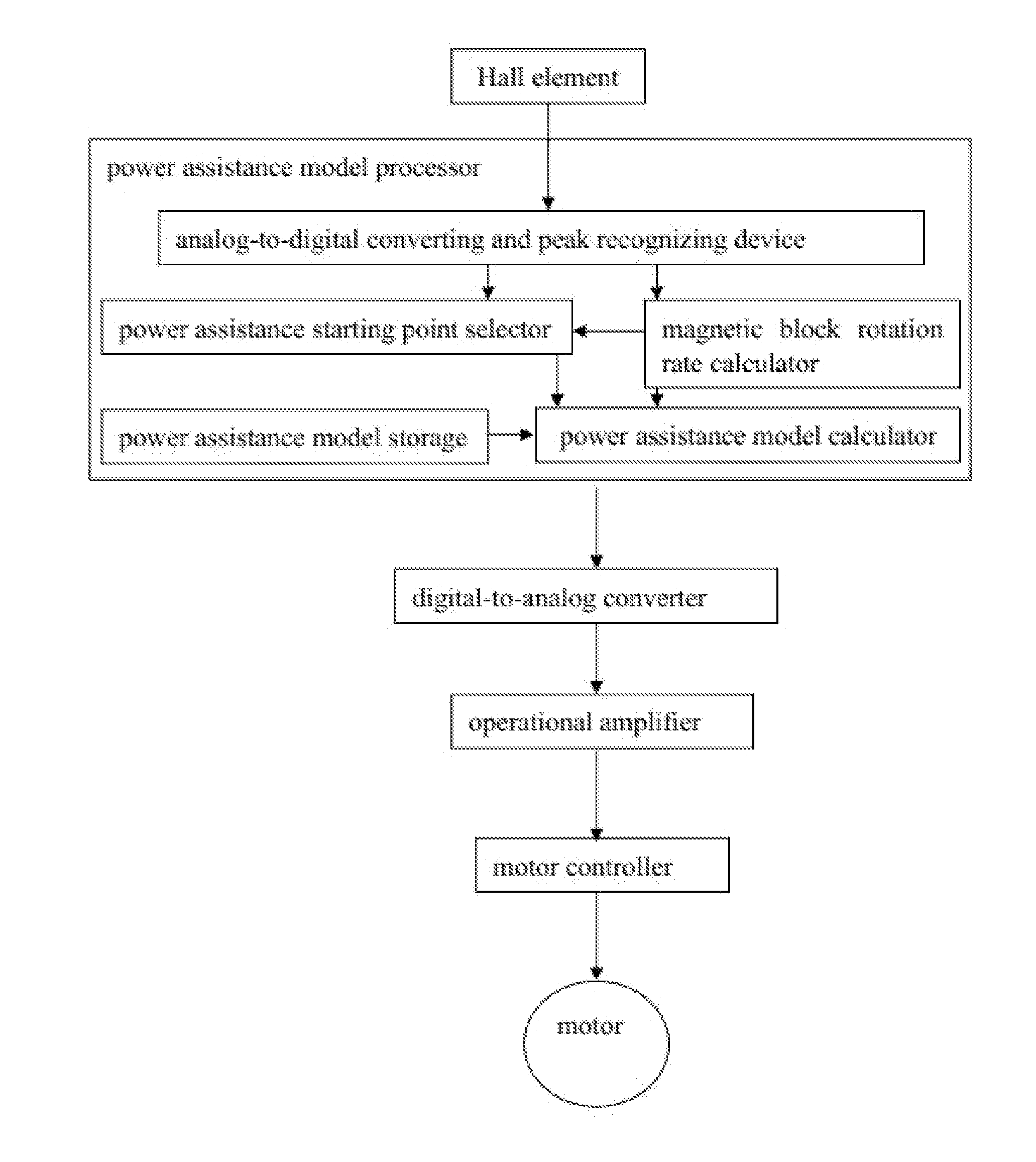
[0126]Referring to FIGS. 1, 3 and 4 of the drawings, the sensor according to this embodiment comprises a sensing element, a power assistance model processor 21, a digital-to-analog converter 27, and an operational amplifier 28 connected in sequence.

[0127][1] The sensing element is adapted for transforming rotational motions of an annular-groove rotating disk 1 to rectangular wave output signals;

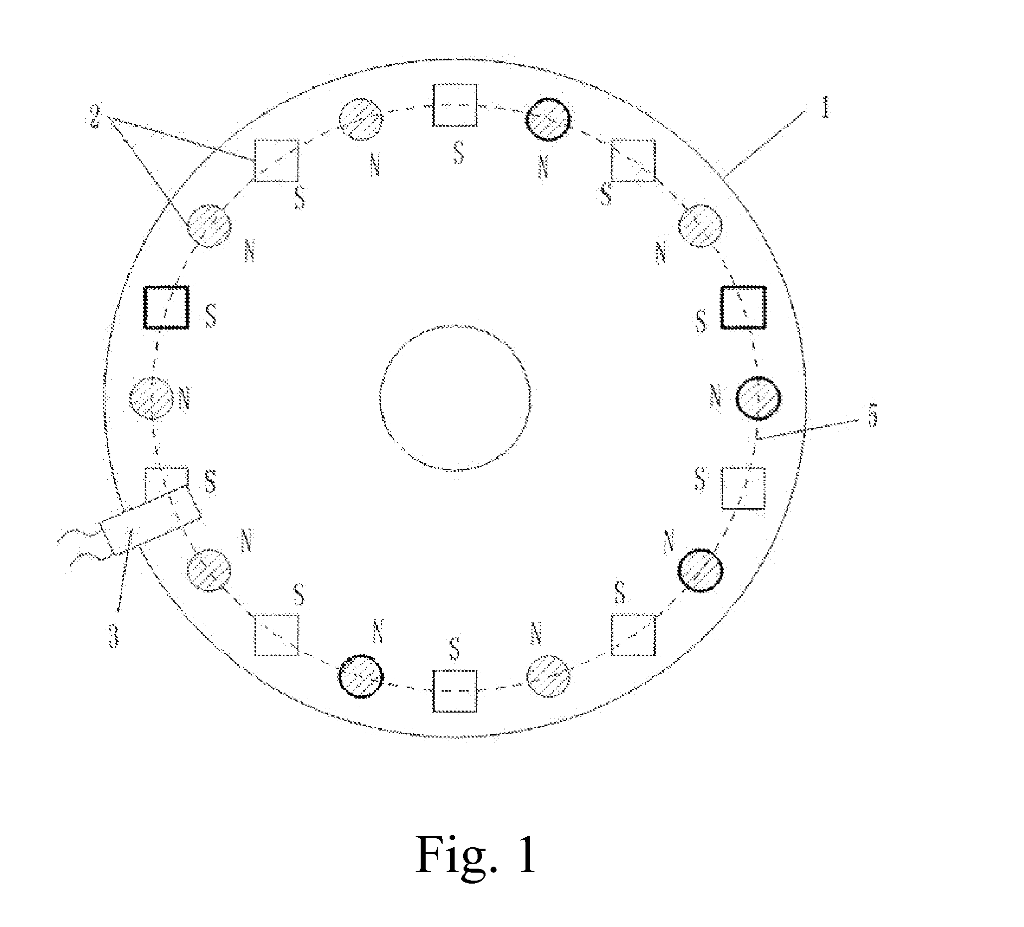
[0128]a concave of the annular-groove rotating disk 1 is opposite to that of the annular-groove fixing disk 40, the annular-groove rotating disk 1 and the annular-groove fixing disk 40 have a certain size such that the annular-groove fixing disk 40 is engaged with an annular groove of the annular-groove rotating disk 1 to form a fitting interior-empty housing in which two disks are capable of relatively rotating with each other, the concave of the annular-groove rotating disk 1 and that of the annular...

example 2

A Sensor Having Multiple Magnetic Blocks of Unevenly Distributed Magnetic Fluxes with High Density in a Housing

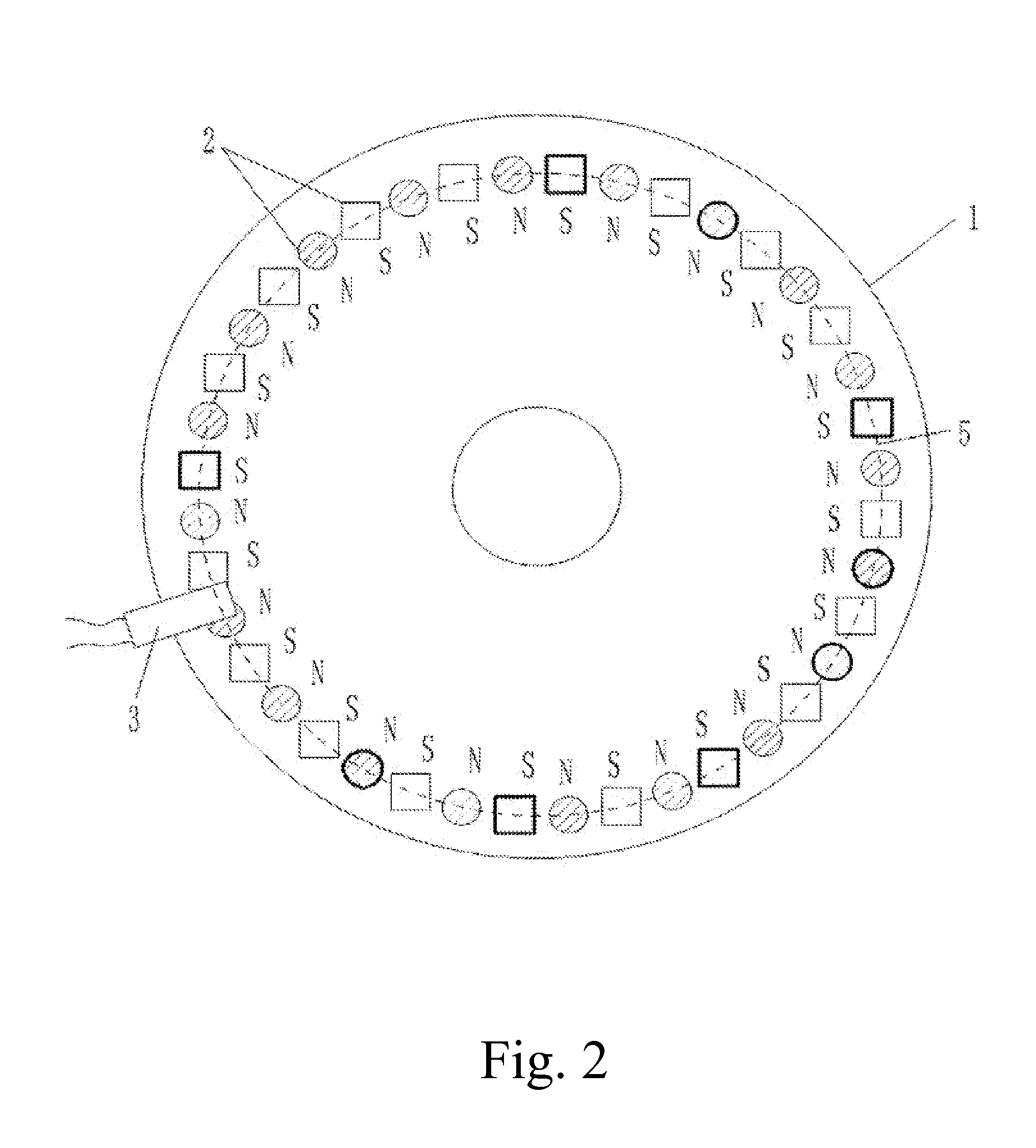
[0144]Referring to FIGS. 2, 3 and 4, a surface diameter of the annular-groove rotating disk 1 within the hollow ring 41 is 10.0 cm. Forty permanent magnetic blocks 2, each of which has a diameter of 0.6 cm and a magnetic flux selected from a range of 146-279 (B·H)max / KJ·m−3, are arranged on the annular-groove rotating disk 1, and the magnetic fluxes of adjacent permanent magnetic blocks 2 are different. A distance between the Hall element 3 and each of the rotating permanent magnetic blocks 2 is kept to 0.2 cm, such that when each of the rotating permanent magnetic blocks 2 passes through the Hall element 3, the Hall element 3 is capable of generating a corresponding rectangular wave electrical signal for outputting. The structures of the annular-groove rotating disk 1, the permanent magnetic blocks 2 and the Hall element 3 are same as those in Example 1.

example 3

A Sensor Having Multiple Magnetic Blocks of Unevenly Distributed Magnetic Fluxes with Concrete Circuits in a Housing

[0145]Referring to FIGS. 1, 3 and 5, the sensor according to the Example 3 comprises a sensing element, a power assistance model processor 21, a digital-to-analog converter 27 and an operational amplifier 28 connected in sequence.

[0146][1] The Hall element 3 is UGN3075; other elements and the structures thereof in the sensing element are same as those in Example 1.

[0147][2] The power assistance model processor 21 selects the single chip microcomputer 31 to complete all functions, the single chip microcomputer 31 is AT89S52, that is to say, that the single chip microcomputer 31 AT89S52 completes all functions of the analog-to-digital converting and wave peak recognizing device 22, the power assistance starting point selector 23, the magnetic block rotation rate calculator 24, the power assistance model storage 25 and the power assistance model calculator 26.

[0148][3] Th...


PUM


Abstract

A sensor having multiple magnetic blocks of unevenly distributed magnetic fluxes in a housing includes, sequentially connected, a sensing element, a power-assisted model processor (21), a digital-to-analog converter (27), and an operational amplifier (28). The sensing element includes a rotating disk (1) and an annular-groove fixing disk (40) fitted therewith. Multiple permanent magnetic blocks (2) are fixedly arranged on the rotating disk (1) in a circular-annular distribution, and at least two of the permanent magnetic blocks (2) are different in magnetic fluxes. On a certain side of the rotating disk (1), the magnetic polarities of adjacent permanent magnetic blocks (2) are opposite, namely, the magnetic polarities of all of the permanent magnetic blocks (2) on the certain side of the rotating disk (1) are distributed in a pattern of pole N, pole S, pole N . . . ; a Hall element (3) on the fixing disk (40) is arranged at a position which is close to the permanent magnetic blocks (2). The N-S distribution of the magnetic polarities of the permanent magnetic blocks (2) allows the Hall element (3) to acquires rectangular wave signals, and to add the digital processing for setting a power assistance model, to allow for expression of the positions of the permanent magnetic blocks (2) on the rotating disk (1), and to determine the uses of different rectangular waves; the relative positions of the permanent magnetic blocks (2) to the Hall element (3) are fixed, and signal output is reliable.

Description

CROSS REFERENCE OF RELATED APPLICATION[0001]This is a U.S. National Stage under 35 U.S.C 371 of the International Application PCT / CN2013 / 076773, filed Jun. 5, 2013, which claims priority under 35 U.S.C. 119(a-d) to CN 201210263503.9, filed Jul. 28, 2012.BACKGROUND OF THE PRESENT INVENTION[0002]1. Field of Invention[0003]The present invention relates to the technical field of the magnetic induction providing signal, and more particularly to the technology of multi-point magnetic induction providing control signal on a rotating part.[0004]2. Description of Related Arts[0005]A Chinese patent application having an application number of CN 201020295192.0 by Yebao automotive materials Industry Co. Ltd disclosed a power-assist bicycle dedicated sensing device which is cooperated by a magnetic part and a flexible assembly and capable of sensing torque. After a long time utilization, changes of spring constants of the flexible assembly lead to changes of control effects of the sensing signal...

Claims


Application Information

Patent Timeline
IPC IPC(8): G01D5/14H03M1/66G01D5/20
CPCG01D5/145H03M1/66G01D5/20G01D5/2451G01P3/487G01L3/101G01D2205/80
Inventor HUANG, QIANG
Owner CHENGDU KUANHE TECH
Why Eureka
Try Eureka