
Radial impeller and casing for centrifugal pump

a centrifugal pump and impeller technology, applied in the direction of machines/engines, stators, liquid fuel engines, etc., can solve the problem of limiting the force applied to fluid flowing fluid, and achieve the effect of reducing the shear for

Active Publication Date: 2015-07-30
MCFINN TECH
View PDF4 Cites 0 Cited by
  • Summary
  • Abstract
  • Description
  • Claims
  • Application Information

AI Technical Summary

Benefits of technology

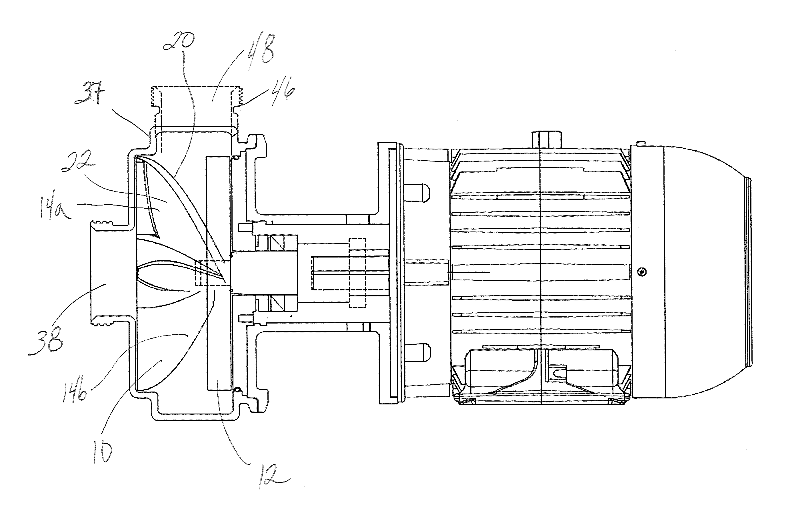
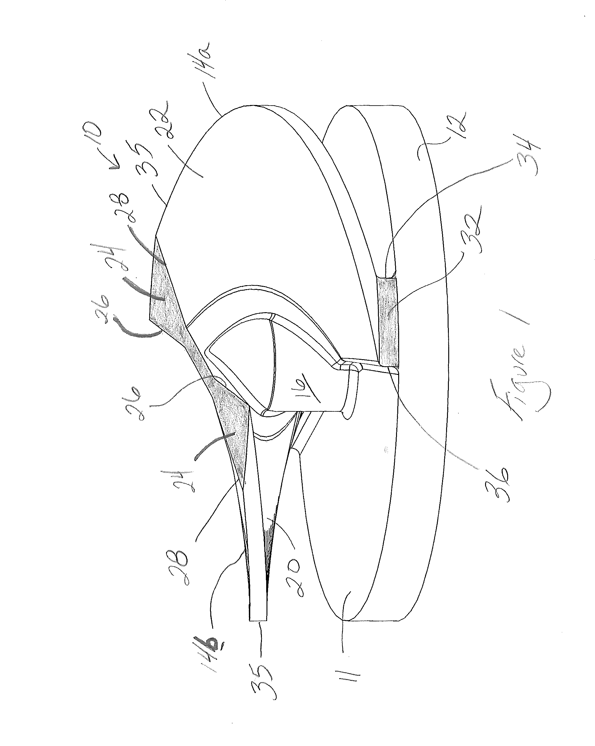
The patent describes a new impeller centrifugal pump that reduces shear forces on the fluid being pumped, which can cause damage and reduce efficiency. The new design uses a smooth path for the fluid, avoids abrupt changes in flow direction, and improves efficiency by reducing recirculation and shearing forces. Additionally, the pump further reduces the rate of acceleration, which can result in high pressure losses, and minimizes damage to the milk being pumped. These technical features make the pump more suitable for various industrial applications, such as food processing and pharmaceutical processing, where reducing damage to the fluid is important.

Problems solved by technology

In particular, the vanes of the impeller, limit the forces applied to fluid flowing past the impeller.

Method used


Image

  • Radial impeller and casing for centrifugal pump
  • Radial impeller and casing for centrifugal pump
  • Radial impeller and casing for centrifugal pump

Examples


example 1

Tests Performed by Silliker, Inc

[0038]The ADV levels of various milk samples were measured before pumping and after pumping using a pump employing the claimed impeller and casing—namely, the Bowpeller model B3258 8″ centrifugal pump—in Trials A and B and a competitor's conventional 8″ centrifugal pump in Trials C and D. The results, summarized in Table 1, show that in Trials C and D, the ADV of the milk consistently increased as a result of pumping using the competitor's conventional pump, thereby indicating undesirable mechanical agitation and foaming of the milk due to pumping. However, Trials A and B show that the ADV of the milk consistently decreased (or at least did not change) as a result of pumping using the claimed impeller and casing—a highly desirable outcome.

example 2

Tests Performed by Eurofins DQCI LLC

[0039]The ADV levels of various milk samples were measured before pumping and after pumping using a pump employing the claimed impeller and casing—namely, the Bowpeller model B15154 4″ centrifugal pump—in Trials E and F and a competitor's conventional 4″ centrifugal pump in Trials G and H. The results, summarized in Table 2, show that in Trials G and H, the ADV of the milk consistently increased as a result of pumping using the competitor's conventional pump, thereby indicating undesirable mechanical agitation and foaming of the milk due to pumping. However, Trials E and F show that the ADV of the milk consistently decreased (or at least did not change) as a result of pumping using the claimed impeller and casing—a highly desirable outcome.

[0040]This data confirms that a pump employing the claimed impeller and casing is capable of pumping shear sensitive liquids (such as milk) without applying damaging forces to the liquid. This result would also ...


PUM


Abstract

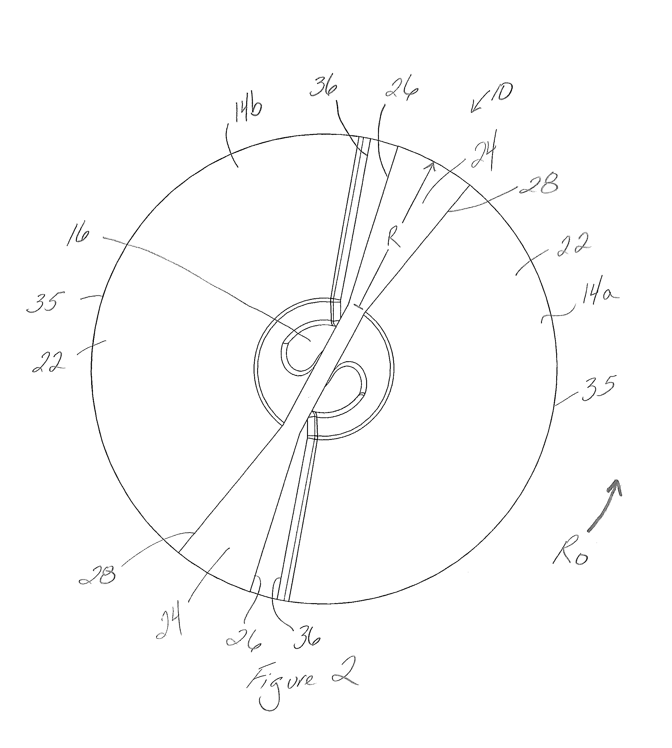
An improved impeller and a casing for a centrifugal pump are disclosed. The impeller comprises vanes which sweep an arc around an impeller axis to provide a smooth path past the impeller and through the pump. The casing is constructed to allow maximum flow rate at the eye of the impeller then shrink the flow channel to reduce internal recirculation promote efficiency, further limiting the effect of damaging forces. The impeller is suited for use in pumps in which a high head is required and in which only low shear forces must be applied to the fluid moving through the pump.

Description

CROSS REFERENCE TO RELATED APPLICATIONS[0001]This patent application makes reference to, claims priority to, and claims benefit from the U.S. Provisional Patent Application Ser. No. 61 / 931,369, filed Jan. 24, 2014. The above-identified application is hereby incorporated herein by reference in its entirety.FIELD OF THE INVENTION[0002]The present invention generally relates to centrifugal pumps, such as, for example, centrifugal pumps having impellers of radial, Francis vane, mixed flow, and axial flow design. More specifically, the present invention relates to an impeller and casing for centrifugal pumps that may produce a high head output and high efficiency, while also being capable of pumping shear sensitive liquids or liquids having suspended solids without applying damaging forces to the liquid or the solids.BACKGROUND OF THE INVENTION[0003]Conventional centrifugal pumps include an impeller that rotates within a cavity in the body of the pump. Fluid entering from an inlet in the...

Claims


Application Information

Patent Timeline
Patent Type & Authority Applications(United States)
IPC IPC(8): F04D1/06F04D29/42
CPCF04D29/4206F04D1/06F04D7/04F04D29/2216F04D29/426
Inventor MCGINN, JOHN J.FINNIGAN, LEROY S.
Owner MCFINN TECH
Learn More