Stacker crane

a technology of a crane and a cylinder head is applied in the field of a stanley crane, which can solve the problems of increasing the possibility of wheel slippage and difficulty in setting the pressurizing force, and achieves the effect of facilitating the setting of the pressurizing force of the drive wheel and controlling other matters

Active Publication Date: 2015-07-30
MURATA MASCH LTD
View PDF12 Cites 4 Cited by
  • Summary
  • Abstract
  • Description
  • Claims
  • Application Information

AI Technical Summary

Benefits of technology

The invention relates to a stacker crane that reduces the impact of wheel pressure fluctuations on the second drive wheel. This allows for a proper pressurizing force to be set without excessively increasing the size of the drive wheels or reducing their lifespan. The crane is also designed to make it easier to control other important factors such as the pressurizing force of the drive wheel. This results in improved performance of the crane and reduces the likelihood of downtime due to maintenance issues.

Problems solved by technology

Furthermore, achieving such performance also increases the possibility of wheel slippage, therefore it becomes necessary to pressurize the wheels.
However, it becomes difficult to set the pressurizing force due to the variations in wheel pressure if the system uses the drive wheels which support the weight of the whole stacker crane.

Method used


Image

  • Stacker crane
  • Stacker crane
  • Stacker crane

Examples


Embodiment Construction

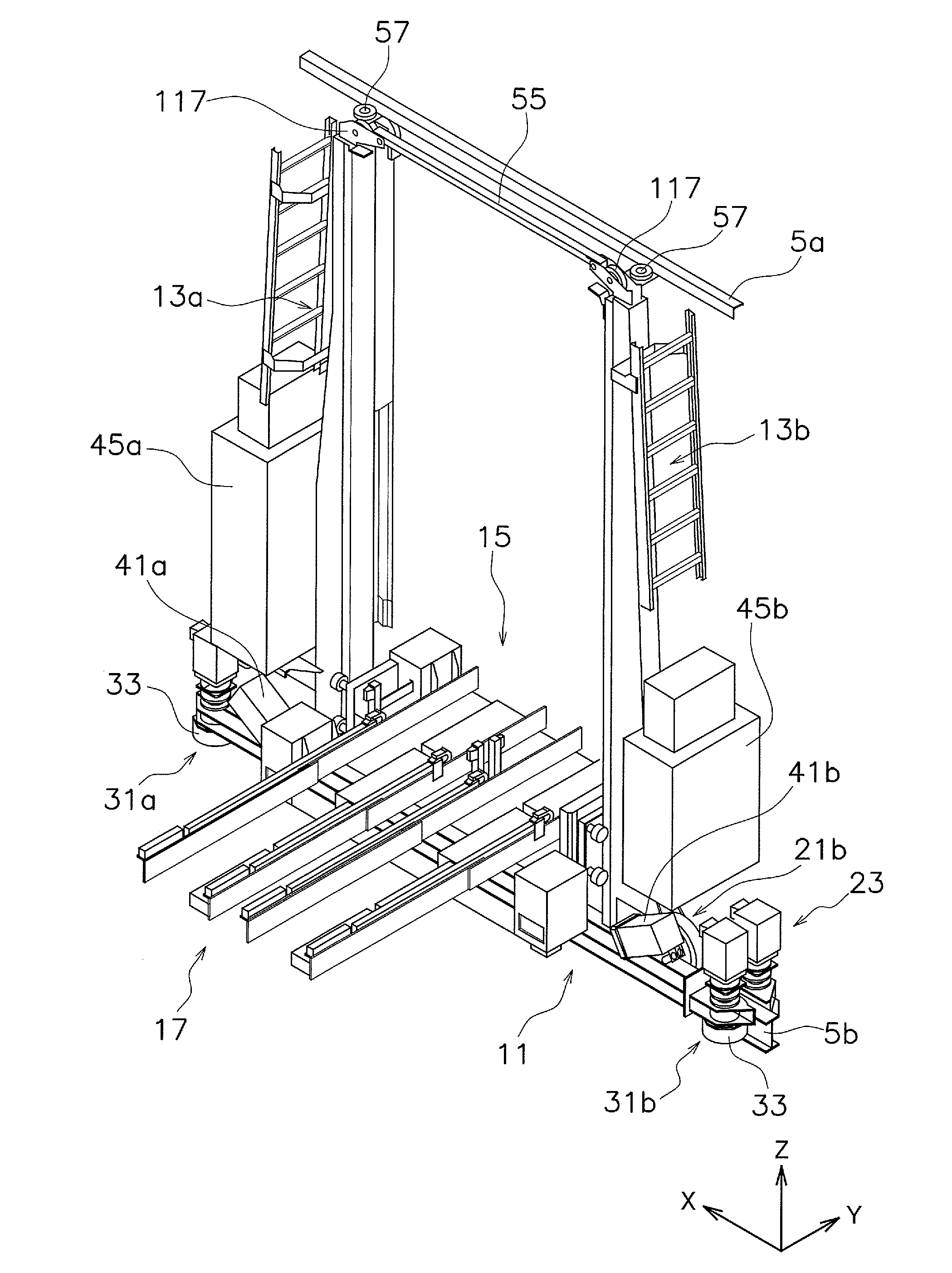
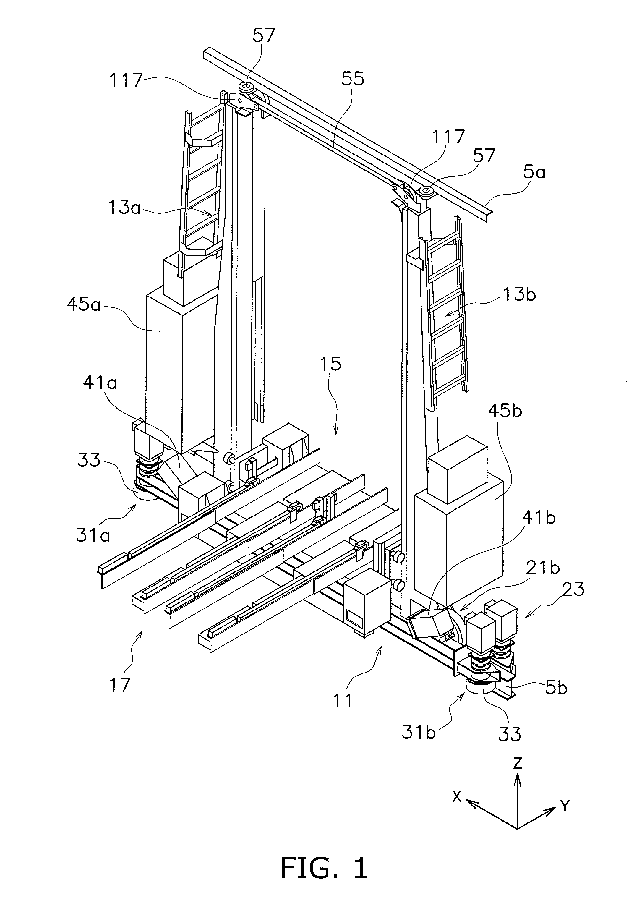
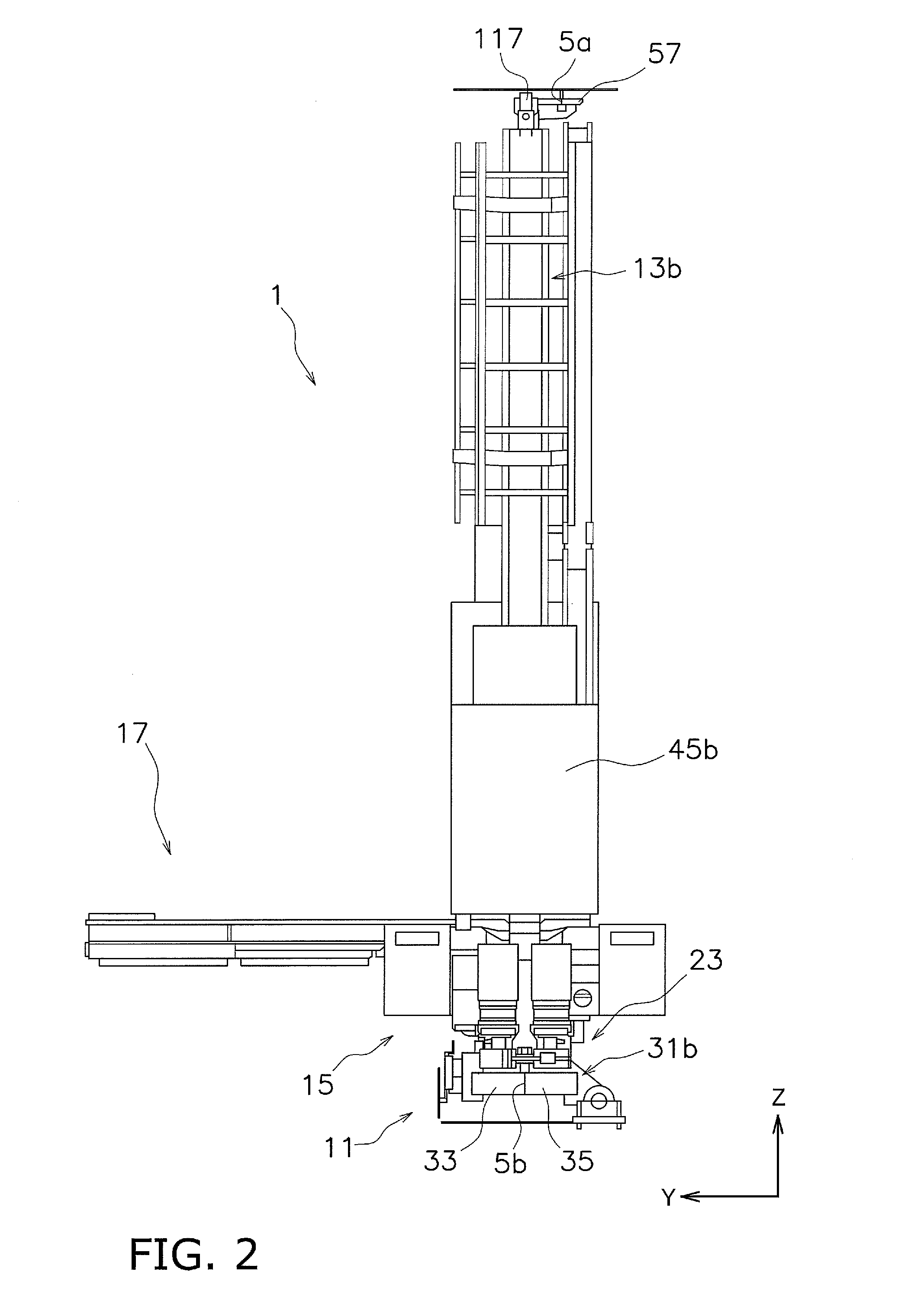
[0045]A stacker crane 1 is an article transfer apparatus that preferably travels inside an automated warehouse (not shown), for example. Below, the travelling direction of the stacker crane 1 is the X direction, and the width direction of the stacker crane 1 is the Y direction (crossing direction that cross the travelling direction). In addition, the vertical direction is the Z direction.

[0046]A pair of racks (not shown) is disposed on both sides of the stacker crane 1, one on each side, in the width direction (Y direction). The pair of racks is disposed to sandwich a travel passageway of the stacker crane 1. The pair of racks include a plurality of article storage shelves (not shown), and articles are loaded on the shelves. A warehousing station (not shown) configured to warehouse the articles is disposed at a lowermost tier of one of the racks, and a delivery station (not shown) configured to deliver the articles is disposed at a lowermost tier of the other rack.

[0047]As shown in ...


PUM


Abstract

First and second masts of a stacker crane are provided in a travelling vehicle main body to be spaced away from each other in an X-direction and extending in a Z-direction. First and second travel wheels are mounted to the travelling vehicle main body to be spaced away from each other in the X-direction, and roll on an upper surface of a lower guide rail. First and second drive wheel units are provided in the travelling vehicle main body to be spaced away from each other in the X direction. Each of the first and second drive wheel units includes a first drive wheel and a second drive wheel. The first drive wheel is in contact with a first side surface of the lower guide rail, and the second drive wheel is pivotably attached to the travelling vehicle main body and urged toward the first drive wheel so that the second drive wheel is in contact with a second surface of the lower guide rail.

Description

BACKGROUND OF THE INVENTION[0001]1. Field of the Invention[0002]The present invention relates to a stacker crane.[0003]2. Description of the Related Art[0004]A conventional automated warehouse includes, for example, a pair of racks, a stacker crane, a warehousing station, and a delivery station. The pair of racks is spaced apart by a prescribed spacing in the forward-rearward direction. The stacker crane is provided moveably in the left-right direction between the front and rear racks. The warehousing station is disposed on a side of one of the racks. The delivery station is disposed on a side of the other one of the racks. The racks have numerous article storage shelves at the top, bottom, left, and right.[0005]The stacker crane includes a travelling truck, a lift platform that is freely elevatable along a mast provided to the travelling truck, and an article transfer apparatus (e.g., a slide fork that is slidably provided in the forward-rearward direction) that is provided to the ...

Claims


Application Information

Patent Timeline
Patent Type & Authority Applications(United States)
IPC IPC(8): B66F9/07B65G1/04
CPCB65G1/0407B66F9/072B66F9/07
Inventor KOYAMA, YOICHIRO
Owner MURATA MASCH LTD
Why Eureka
Try Eureka