
Device for manufacturing three-dimensional objects using superimposed layers, and associated method of manufacture

a three-dimensional object and superimposed layer technology, applied in the direction of additive manufacturing processes, manufacturing tools, electric/magnetic/electromagnetic heating, etc., can solve the problem of first limitation of the known manufacturing installation using superimposed layer laser treatment, and size limitation

Active Publication Date: 2015-07-30
PHENIX SYST
View PDF2 Cites 77 Cited by
  • Summary
  • Abstract
  • Description
  • Claims
  • Application Information

AI Technical Summary

Benefits of technology

The patent describes a device and method for making three-dimensional objects using layers that are superimposed. The device has a mechanism for moving a galvanometric head into different positions, which creates an effective sintering zone for each position. The method has the same advantages as the device, such as the ability to create complex objects with precise dimensions and strength.

Problems solved by technology

This is a first limitation of the known manufacturing installations using laser treatment with superimposed layers.
It thus appears that the known manufacturing installations using the laser treatment with superimposed layers do not allow homogenous treatment of the layer over the entire possible maximum sintering zone, the size of which is also limited.

Method used


Image

  • Device for manufacturing three-dimensional objects using superimposed layers, and associated method of manufacture
  • Device for manufacturing three-dimensional objects using superimposed layers, and associated method of manufacture
  • Device for manufacturing three-dimensional objects using superimposed layers, and associated method of manufacture

Examples


first embodiment

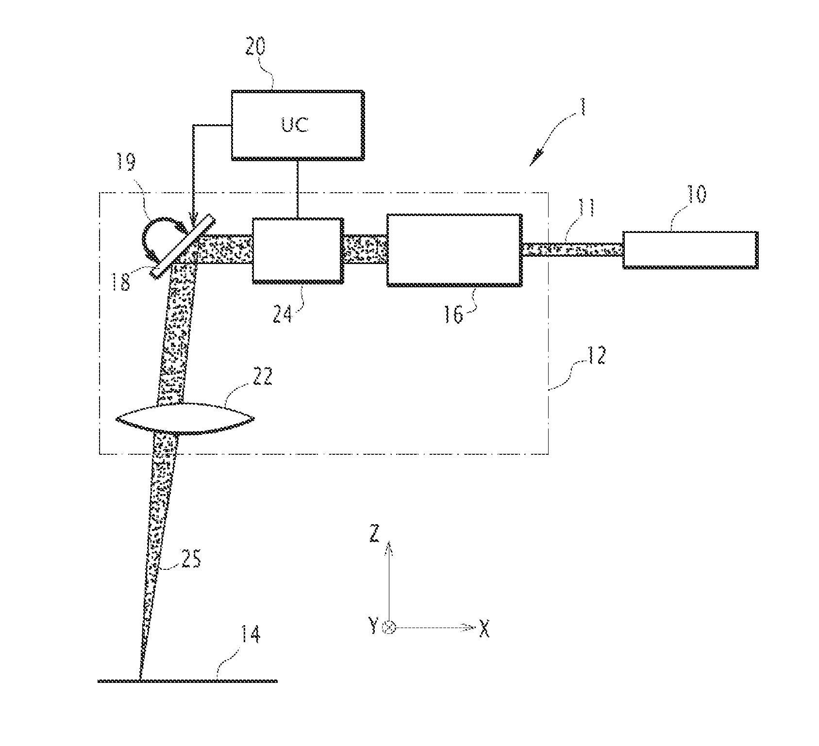
[0051]The galvanometric head 12 also comprises a device making it possible to focus the laser beam in the sintering field 14 which, is a flat field lens 22, known as an F-Theta lens, placed downstream from the beam deflecting means 18.

second embodiment

[0052] the device making it possible to focus the laser beam in the sintering field 14 is a so-called “third axis” device 24, modifying the focal distance, placed upstream from the beam deflecting means 18. In one embodiment, the device 24 is a lens motorized along the axis of the beam 11. Alternatively, the device 24 is a variable focus lens. The central unit 20 is also capable of steering the device 24 in order to adjust the focal distance.

third embodiment

[0053] the device making it possible to focus the laser beam in the sintering field 14 is made up of a combination of a “third axis” type device and a flat field focusing lens.

[0054]The beam 25 coming from the galvanometric head 12 intersects the sintering field 14. The physical limits of the movement of the beam 25 in the sintering field, in particular due to the angular travel of the mirrors making up the deflecting means 18, define a maximum sintering zone in the sintering field. For example, for an angular travel of the mirrors bounded to + / −20 degrees, and a distance separating the last diopter of the galvanometric head from the sintering field of 500 mm, called working distance, the maximum sintering zone is a square with sides measuring 290 mm in the first embodiment with a flat field lens 22 and 418 mm for the second embodiment with a so-called “third axis” device 24.

[0055]The galvanometric head 12 and the laser electromagnetic energy source 10 form an optical treatment chai...


PUM

PropertyMeasurementUnit
diameteraaaaaaaaaa
diameteraaaaaaaaaa
travel angleaaaaaaaaaa

Abstract

A device for manufacturing three-dimensional objects using superimposed layers is capable, for each layer to be manufactured, of applying a laser beam treatment to a layer of a pulverulent material or liquid placed in a sintering field. The device includes a galvanometric head able to steer a laser beam toward each point of a maximum sintering zone of the sintering field when the galvanometric head is positioned at a predetermined position. The device further includes limiting elements for limiting the steering of the laser beam to an effective sintering zone situated inside the maximum sintering zone, and movement elements for moving the galvanometric head in a plane parallel to that of the sintering field, allowing the galvanometric head to be positioned at at least two different positions, an effective sintering zone being associated with each position of the galvanometric head. An associated method of manufacturing three-dimensional objects is described.

Description

FIELD OF THE INVENTION[0001]The present invention relates to a device for manufacturing three-dimensional objects using superimposed layers, able to apply, for each layer to be manufactured, laser beam solidification of a layer of a powdery or liquid material placed in a sintering field and an associated manufacturing method.[0002]The invention falls in the technical field of producing three-dimensional objects by laser treatment, in particular by laser sintering.DESCRIPTION OF THE PRIOR ART[0003]It is known to produce three-dimensional objects with any shape whatsoever using layer-by-layer additive manufacturing by laser sintering. Such a manufacturing method includes depositing a layer of powdery or liquid material on a substrate, which may be a previously solidified layer of the object to be manufactured. The layer of powdered or liquid material is gradually solidified by applying a laser beam, also called lasing, in a zone defined by a two-dimensional section of the object to be...

Claims


Application Information

Patent Timeline
Patent Type & Authority Applications(United States)
IPC IPC(8): B29C67/00
CPCB29C67/0088B33Y10/00B33Y30/00B29C67/0074B23K26/0876B23K26/34B23K26/082B29C64/135B29C64/153B29C64/393B29C64/141Y02P10/25B22F10/28B22F12/44B22F10/366B22F12/45B22F12/49
Inventor TEULET, PATRICK
Owner PHENIX SYST
Learn More