Optical phase device, method and system
a phase device and optical technology, applied in the field of sensing technology and dispersion compensation technology, can solve the problems of increasing the difficulty of detection, unavoidable existing structures, and low signal-to-noise ratio
- Summary
- Abstract
- Description
- Claims
- Application Information
AI Technical Summary
Benefits of technology
Problems solved by technology
Method used
Image
Examples
example 1
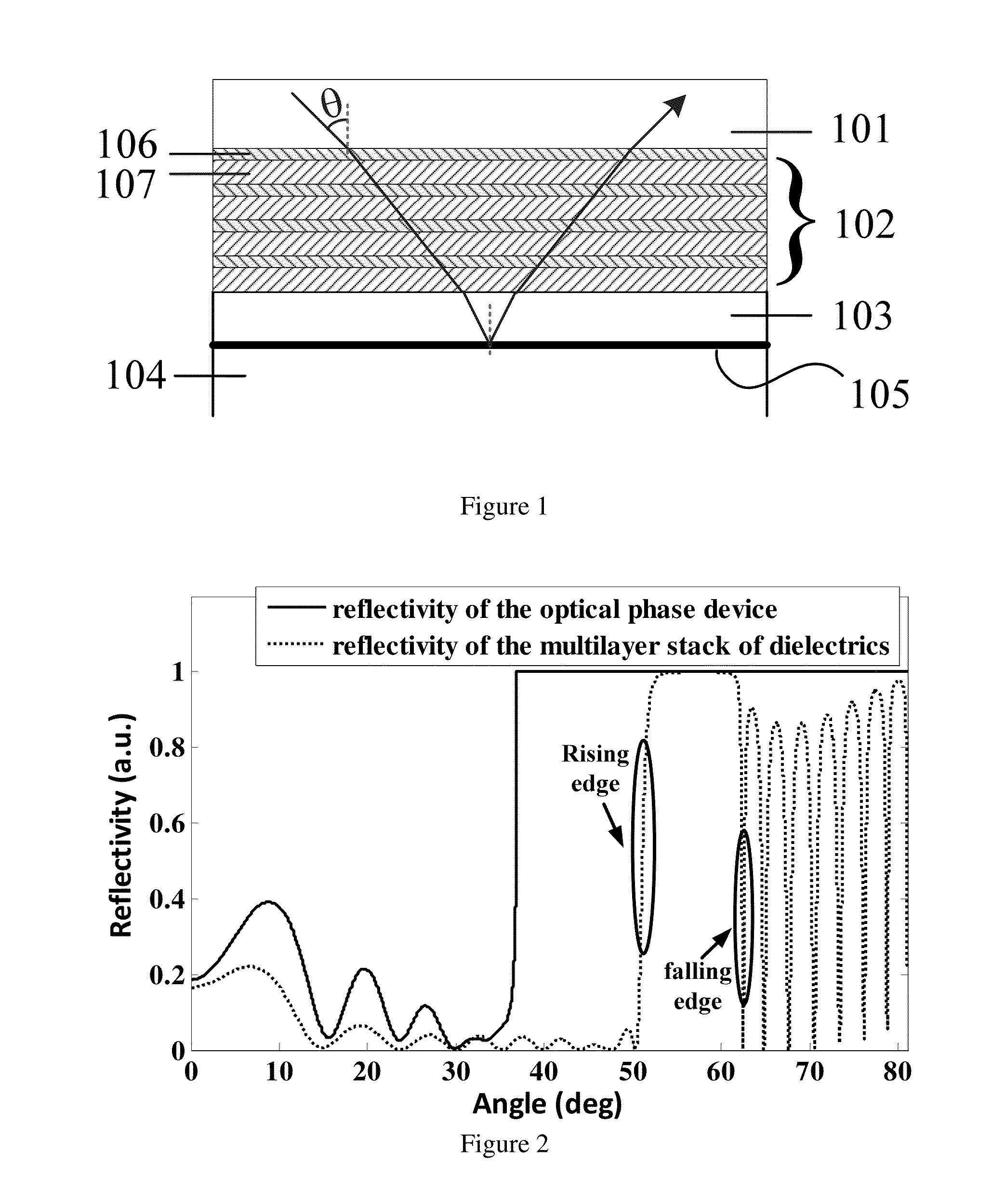
[0082]FIG. 1 shows the schematic diagram of an optical phase device provided by our invention.
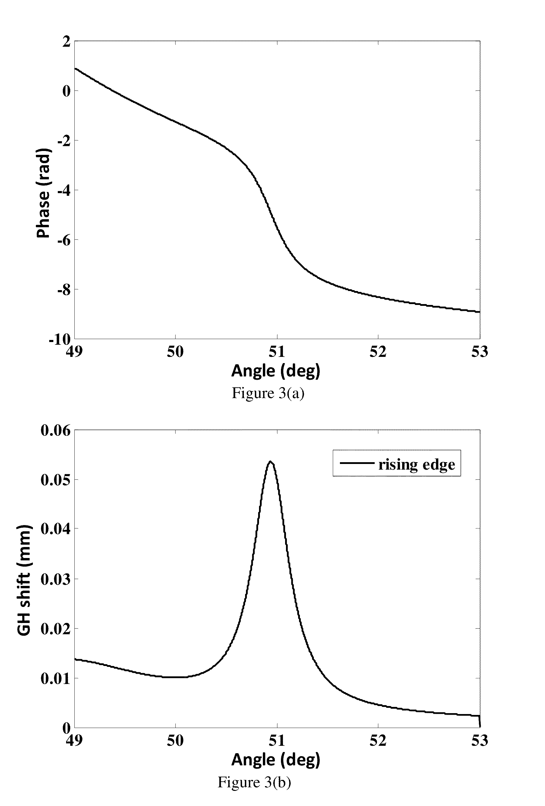
[0083]In this example, the polarization of the input light is TM polarization, and the wavelength is set as 980 nm. The material of the transparent dielectric substrate 101 is ZF10 glass with its refractive index of 1.668. The material of each layer in the multilayer stack of dielectrics 102 is supposed to be ideal transparent dielectric, where there is neither absorption loss, nor interface dispersion loss between each layer. The material of the high refractive index dielectric thin layer 106 is titanium dioxide with its refractive index of 2.3, and the material of the low refractive index dielectric thin layer 107 is silica dioxide with its refractive index of 1.434; the material of the buffer layer 103 is titanium dioxide as well; the external medium 104 is air. In this example the critical angle of the total reflection on the reflection surface 105 is 36.83 degrees, which is the inciden...
example 2
[0087]In this example, the polarization of the input light is TM polarization, and the wavelength is set as 980 nm. For the optical device structure shown in FIG. 1, the material of the transparent dielectric substrate 101 is ZF10 glass whose refractive index is 1.668; for the multilayer stack of dielectrics, the high refractive index dielectric thin layer 106 and the low refractive index dielectric thin layer 107 are arranged alternatively for 10 periods, wherein the material of the high refractive index dielectric thin layer 106 is titanium dioxide with refractive index of 2.3 and thickness as 196.7 nm; the material of the low refractive index dielectric thin layer 107 is silica with refractive index of 1.434 and thickness as 365.3 nm; the material of the buffer layer 103 is titanium dioxide with refractive index of 2.3 and thickness as 20 nm.
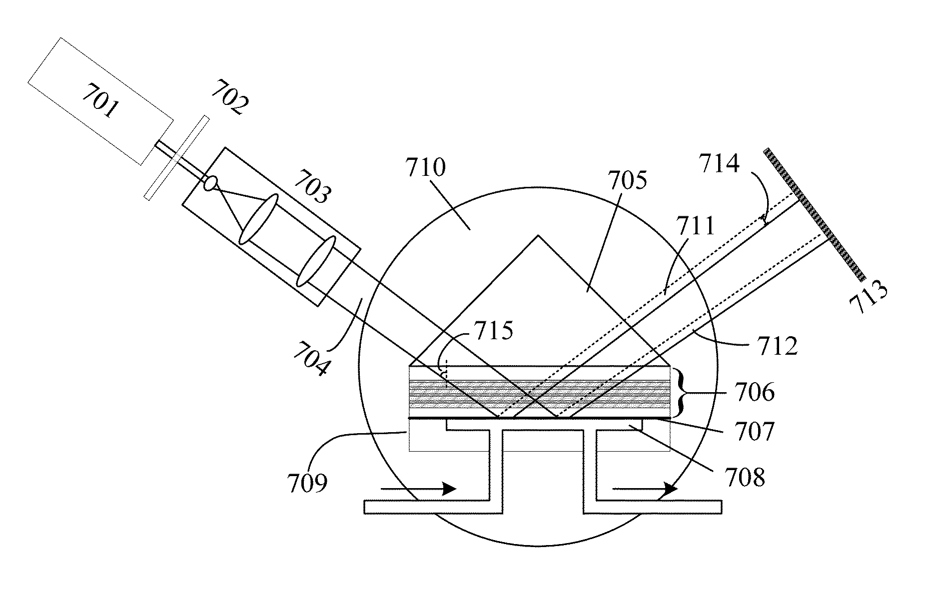
[0088]The optical phase device described above is used for Goos-Hanchen sensing detection, and the test sample is NaCl aqueous solutions of ...
example 3
[0111]The schematic diagram of the optical phase device used in this embodiment is as shown in FIG. 1. The material of the transparent dielectric substrate 101 is ZF1 glass. The multilayer stack of dielectrics 102 consists of 14 periods, and for each period, the high refractive index dielectric thin layer 106 is a layer of tantalum oxide with thickness of 264 nm and the low refractive index dielectric thin layer 107 is a 184 nm thick layer of silica. The buffer layer 103 is a layer of tantalum oxide of 21 nm thick, and the external medium 104 is air. The working range of the wavelength is 760-790 nm and the refractive index of each layer described above can be calculated through Sellmeier equation. By designing the thickness of each layer, high reflectivity region of this optical phase device can be designed.
[0112]When the incident angle is 60 degrees, the curve of the phase variation Δφ of multi-layer dielectric 102 against the wavelength λ of the incident beam for TM polarization ...
PUM
 Abstract
Description
Claims
Application Information
 - R&D
- Intellectual Property
- Life Sciences
- Materials
- Tech Scout
- Unparalleled Data Quality
- Higher Quality Content
- 60% Fewer Hallucinations
Browse by: Latest US Patents, China's latest patents, Technical Efficacy Thesaurus, Application Domain, Technology Topic, Popular Technical Reports.
© 2025 PatSnap. All rights reserved.Legal|Privacy policy|Modern Slavery Act Transparency Statement|Sitemap|About US| Contact US: help@patsnap.com


