Device for producing direct current passing into load power-supply circuits

a technology of direct current and power supply circuit, applied in the field of electric engineering, can solve the problem of low dissipation power of dc stabilizer, and achieve the effect of enhancing efficiency

Active Publication Date: 2015-07-16
DRIVE CJSC
View PDF1 Cites 13 Cited by
  • Summary
  • Abstract
  • Description
  • Claims
  • Application Information

AI Technical Summary

Benefits of technology

[0015]In this way, the dissipation power at the MOP-transistor (15) becomes likewise stabilized and essentially load-change unaffected which results ultimately in substantial enhancing efficiency in which achieving the above-identified technical result manifests itself.

Problems solved by technology

The technical result, which either of the above prior art fails to achieve, is stabilizing voltage drop at the DC stabilizer that results in lower dissipation power in the DC stabilizer when load impedance varies.

Method used


Image

  • Device for producing direct current passing into load power-supply circuits
  • Device for producing direct current passing into load power-supply circuits

Examples


Embodiment Construction

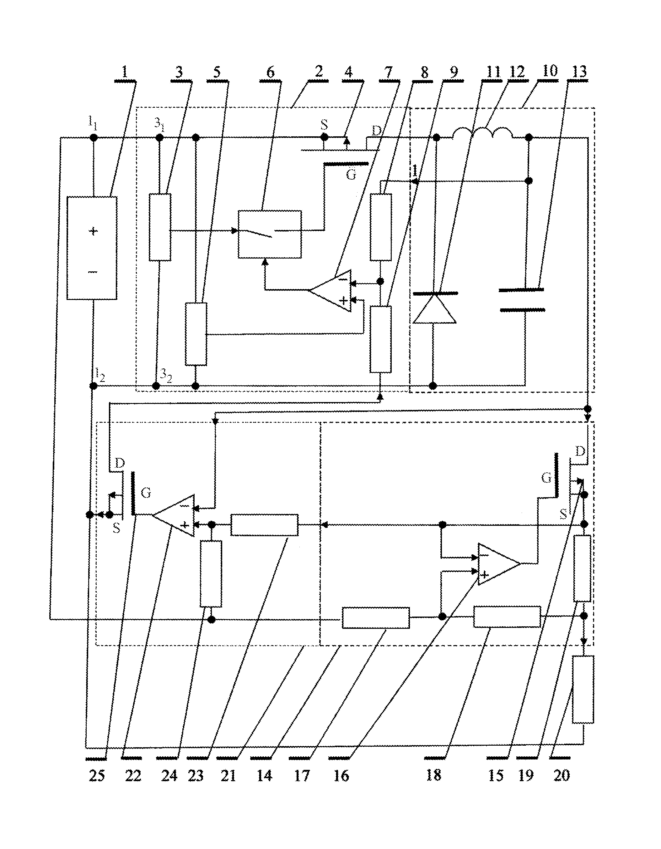
[0018]The present apparatus for providing load constant current comprises:[0019]a DC voltage source 1 that may include, for example, a full wave rectifier with a filter;[0020]a DC-to-pulse voltage converter 2 comprising: a constant frequency square pulse generator 3 connected by its terminals (which are the DC-to-pulse voltage converter 2 first and second inputs) in parallel to the DC voltage source 1 first and second terminals; a MOP-transistor 4 connected by its source to the DC voltage source 1 first terminal; a reference voltage source 5 connected by its inputs in parallel to the constant frequency square pulse generator 3 terminals; controllable gate circuit 6 connected by its (information) input to an output of the constant frequency square pulse generator 3 and by its output—to the MOP-transistor 4 gate; OA 7 connected by its output to a control input of the controllable gate circuit 6 and by its non-inverting (“+”) input—to a reference voltage source 5 output; a first resist...


PUM


Abstract

The apparatus, of the field of electrical engineering, comprises a DC voltage source (DCVS), a DC-to-pulse voltage converter (DCPVC), a pulse-to-DC voltage converter (PDCVC), a DC stabilizer (DCS) and a control circuit (CC). The DCPVC is connected to the DCVC by its inputs and to the PDCVC by its outputs. A PDCVC output is connected to the DCPVC first control input and to a DCS first input, whose second input is connected to a DCVS positive output and whose first output is an apparatus output. A CC first input is connected to the PDCVC output, a CC second input is connected to a DCS second output, a CC first output is connected to a DCVS negative output, and a CC second output is connected to a DCPVC second control input.
The result is the stabilization of dissipation power in the stabilizer.

Description

CROSS-REFERENCE TO RELATED APPLICATIONS[0001]This application is a U.S. National phase application of International application PCT / RU2013 / 000785 filed on Sep. 10, 2013, which claims priority from Russian application 2012133772 filed on Aug. 7, 2012, the International and Russian applications being hereby incorporated by reference in their entirety.BACKGROUND OF THE INVENTION[0002]1. Field of the Invention[0003]The present invention relates to electrical engineering and can be used in power supply of higher efficiency.[0004]2. Description of the Related Art[0005]Known in the art is a LED light source (RU 93611U1, published on Apr. 27, 2010) which comprises the following features: AC / DC voltage converter; capacitor filter connected with its terminals to outputs of the AC / DC voltage converter; DC / DC down voltage converter connected by its inputs to the capacitor filter terminals; a DC stabilizer including a voltage stabilizer and a resistor connected by one of its terminals to a volta...

Claims


Application Information

Patent Timeline
Patent Type & Authority Applications(United States)
IPC IPC(8): G05F3/16
CPCG05F3/16H02M3/156H02M3/1588Y02B70/10
Inventor ROMANOV, YURIY I.
Owner DRIVE CJSC
Why Eureka
Try Eureka