Methods and systems for monitoring well integrity and increasing the lifetime of a well in a subterranean formation

a technology of subterranean formation and well integrity, which is applied in the direction of survey, borehole/well accessories, etc., can solve the problems of cement deformation, cracking, cement deformation, corrosion, scaling and/or other degradation of equipment within the well, etc., and achieve the effect of reducing degradation

Inactive Publication Date: 2015-07-16
BAKER HUGHES INC
View PDF7 Cites 17 Cited by
  • Summary
  • Abstract
  • Description
  • Claims
  • Application Information

AI Technical Summary

Benefits of technology

The patent text describes systems and methods for monitoring the integrity of a well and reducing degradation of wellbore components. The systems use thermodynamic and chemical reaction kinetics to predict which reactions are likely to occur and which properties of the fluid exiting the wellbore will be affected. These predictions are then used to adjust or detect the composition of the injected fluid and prevent damage to the wellbore equipment. Overall, the technology helps to improve the efficiency and prevent failures in drilling and wellbore construction.

Problems solved by technology

Depending on their chemical properties, these fluids, which may be characterized generally as “corrosive fluids,” may react with some of the materials within the well and with each other, causing corrosion, scaling and / or other degradation of the equipment within the well.
Although the downhole equipment may be in contact with such fluids for only short periods of time, such as during drilling or stimulation, considerable degradation of equipment may take place due to the contact and interaction with the fluids.
In addition, exposing cement within a well to formation fluids, drilling fluids, completion fluids, injected fluids, stimulation fluids, and mixtures thereof may cause the cement to degrade and crack.

Method used


Image

  • Methods and systems for monitoring well integrity and increasing the lifetime of a well in a subterranean formation
  • Methods and systems for monitoring well integrity and increasing the lifetime of a well in a subterranean formation
  • Methods and systems for monitoring well integrity and increasing the lifetime of a well in a subterranean formation

Examples


Embodiment Construction

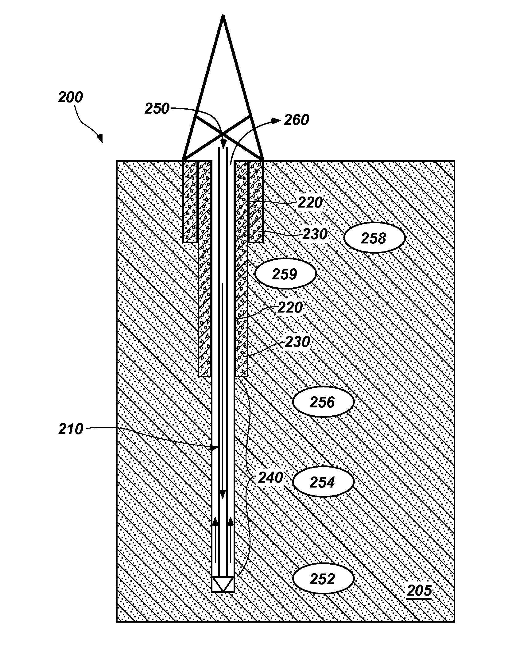
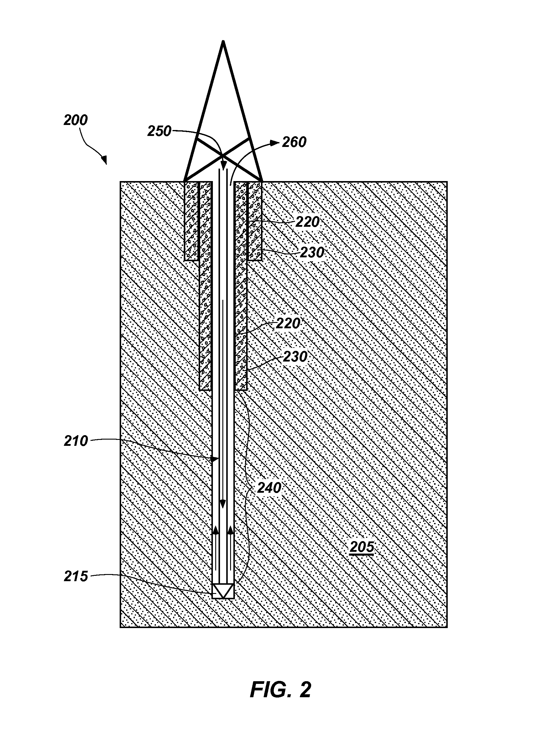
[0018]The illustrations presented herein are not meant to be actual views of any particular material, apparatus, system, or method, but are merely idealized representations that are employed to describe certain embodiments of the present invention. For clarity in description, various features and elements common among the embodiments of the invention may be referenced with the same or similar reference numerals.

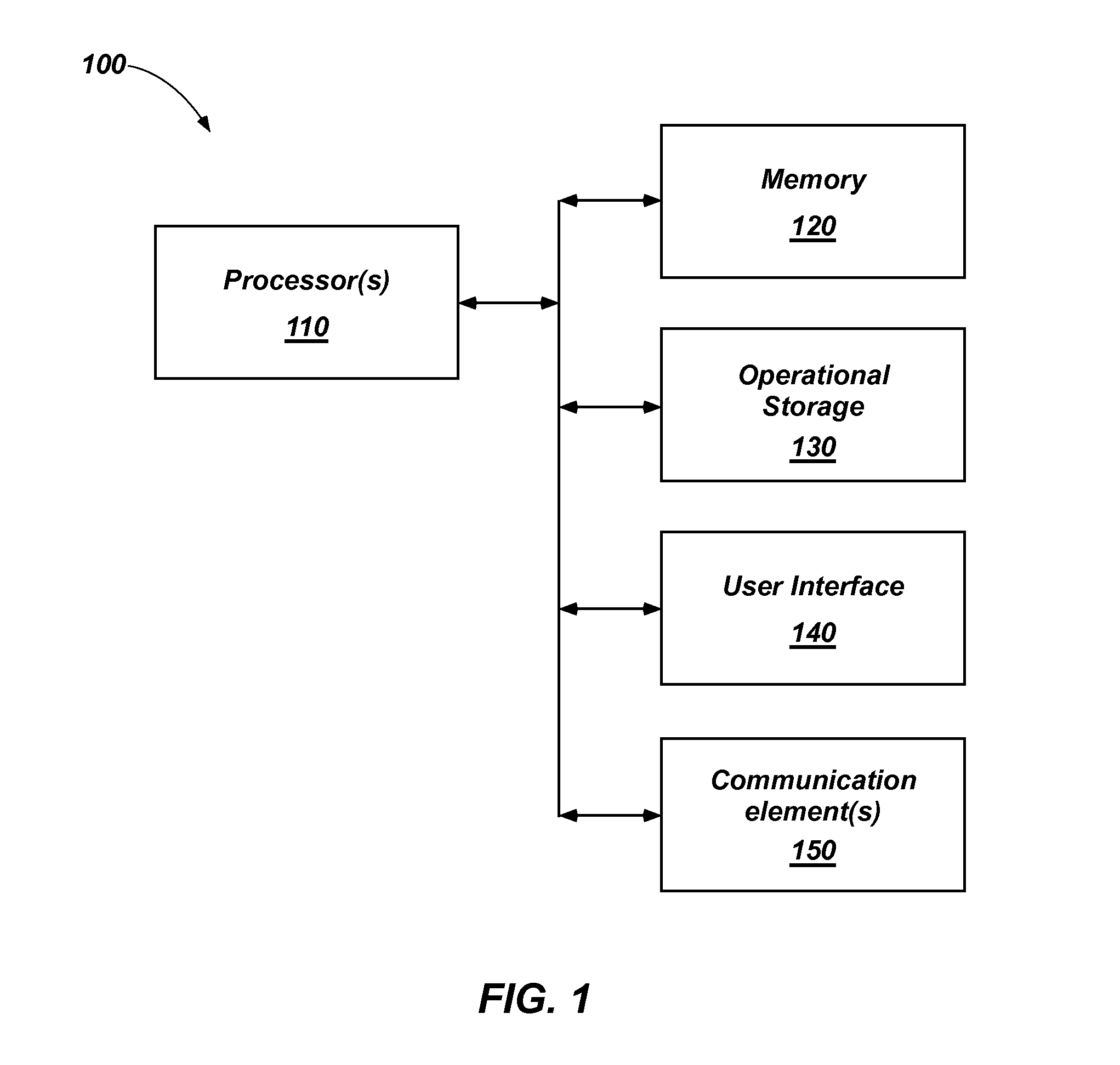
[0019]Those of ordinary skill would appreciate that the various illustrative logical blocks, modules, circuits, and algorithm acts described in connection with embodiments disclosed herein may be implemented as electronic hardware, computer software, or combinations of both. To clearly illustrate this interchangeability of hardware and software, various illustrative components, blocks, modules, circuits, and acts are described generally in terms of their functionality. Whether such functionality is implemented as hardware or software depends upon the particular application an...


PUM


Abstract

A system for increasing the detecting degradation of a wellbore. The system comprises a computer memory configured for storing computing instructions and a processor operably coupled to the computer memory. The system comprises a sensor operably coupled to the computer memory and is configured to determine the presence of at least one chemical species indicative of degradation of the wellbore in a fluid exiting the wellbore. Methods of monitoring a wellbore for corrosion or other degradation of one or more components of wellbore equipment are disclosed as are methods of increasing the lifetime of a wellbore.

Description

CROSS-REFERENCE TO RELATED APPLICATION[0001]This application claims the benefit of U.S. Provisional Patent Application Ser. No. 61 / 927,735, filed Jan. 15, 2014, and entitled “METHODS AND SYSTEMS FOR MONITORING WELL INTEGRITY IN A SUBTERRANEAN FORMATION,” the disclosure of which application is hereby incorporated herein in its entirety by reference.FIELD[0002]Embodiments of the disclosure relate generally to methods and systems for monitoring a downhole environment for corrosion and degradation of downhole equipment and components during downhole operation such as drilling of a wellbore, formation stimulation, and production.BACKGROUND[0003]During the lifetime of a well, the equipment used to construct and produce from the well may interact with different types of fluids, such as drilling fluids, stimulation fluids, completion fluids, formation fluids, fluids injected into an adjacent well, etc. Depending on their chemical properties, these fluids, which may be characterized generall...

Claims


Application Information

Patent Timeline
Patent Type & Authority Applications(United States)
IPC IPC(8): E21B49/08
CPCE21B49/08E21B49/00E21B47/00E21B49/081E21B49/0875C09K8/032C09K8/035C09K8/528C09K8/60C09K8/605C09K2208/32E21B41/02E21B43/25E21B49/02
Inventor BARTETZKO, ANNELEHR, JOERGKLAPPER, HELMUTH SARMIENTODAVIDSON, MARCUSBOZAU, ELKE
Owner BAKER HUGHES INC
Why Eureka
Try Eureka