
Electrolytic capacitor-less ac/dc converter and controlling method thereof

a technology of ac/dc converter and capacitor, which is applied in the direction of electric variable regulation, process and machine control, instruments, etc., can solve the problems of blinding light phenomenon, and achieve the effects of simple voltage feedback control, small capacitance, and long service li

Active Publication Date: 2015-06-25
NAT CHENG KUNG UNIV
View PDF5 Cites 18 Cited by
  • Summary
  • Abstract
  • Description
  • Claims
  • Application Information

AI Technical Summary

Benefits of technology

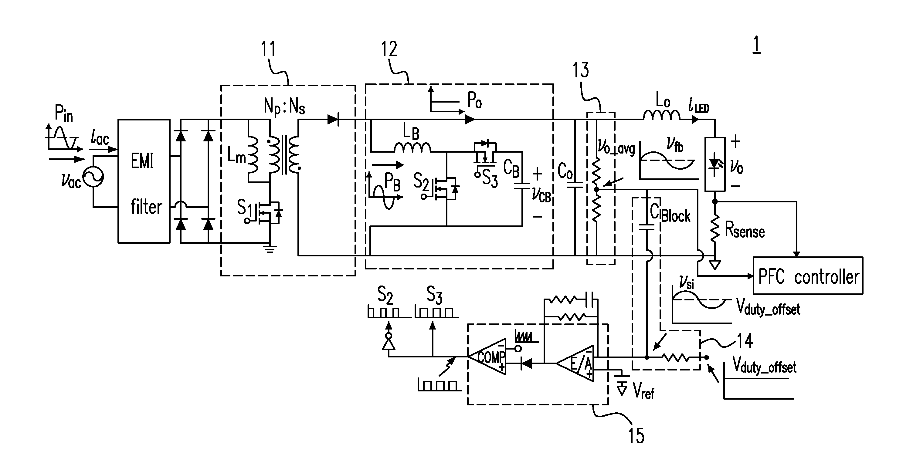
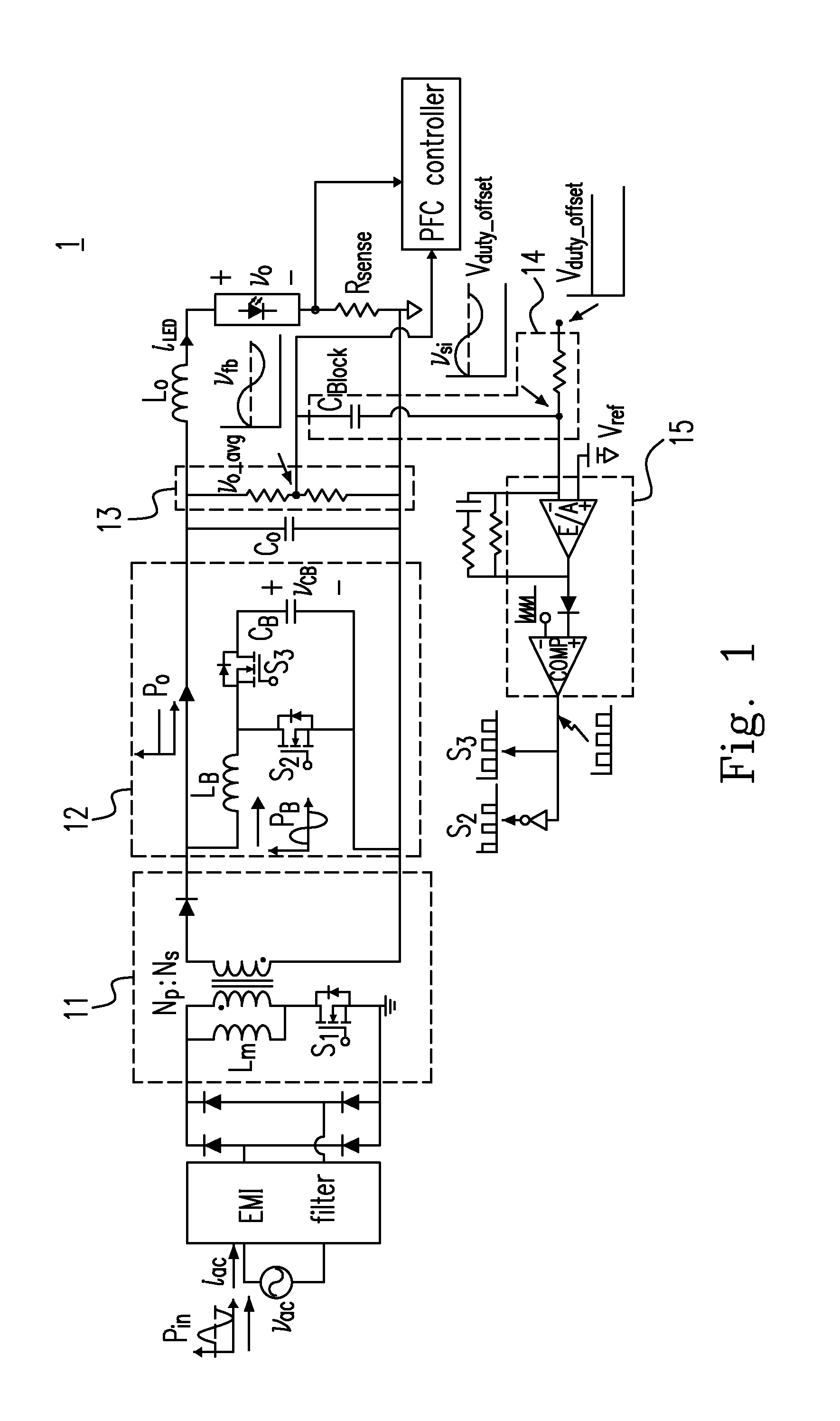
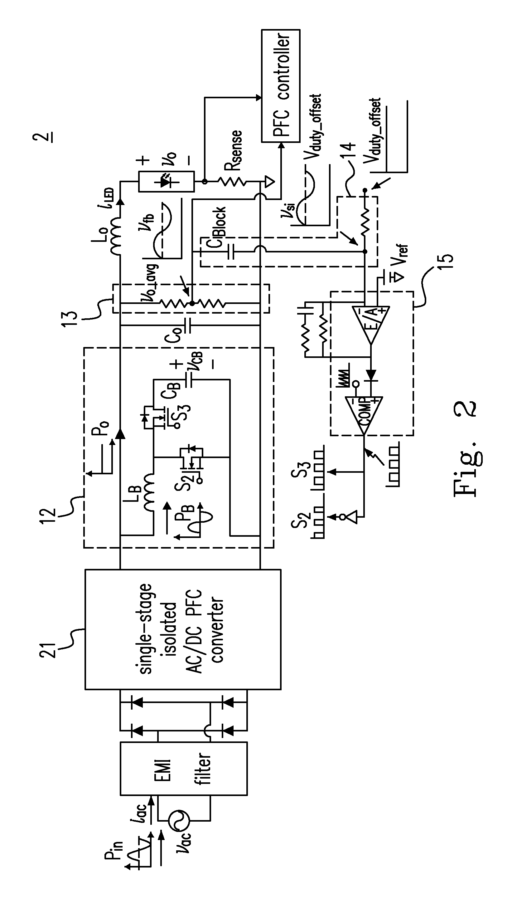
The present invention provides an AC / DC converter with a small output capacitance and a long lifespan. It uses a current ripple eliminator with a simple voltage feedback control to achieve the requirement of smaller output voltage ripple components without using an electrolytic capacitor. The converter includes a non-isolated PFC converter, a current ripple eliminator, a first capacitor, and a voltage feedback control circuit. The voltage feedback control circuit includes a first voltage divider and a buffer resistor to generate a control feedback signal based on the output voltage. The control feedback signal is used to control the input power and the output power of the current ripple eliminator to minimize the ripple of the output power of the converter. The invention also provides an AC / DC converter with a single-stage AC / DC PFC circuit, a current ripple eliminator, and a voltage feedback control circuit to minimize the ripple of the output power. The current ripple eliminator has an input terminal, an energy storage capacitor, and an output terminal to accurately determine when the energy storage capacitor should store or release the electric energy to minimize the ripple of the output power.

Problems solved by technology

If electrolytic capacitors having large capacitance are not used, then the output voltage (current) fluctuates, which results in a blinking light phenomenon.

Method used


Image

  • Electrolytic capacitor-less ac/dc converter and controlling method thereof
  • Electrolytic capacitor-less ac/dc converter and controlling method thereof
  • Electrolytic capacitor-less ac/dc converter and controlling method thereof

Examples


embodiment 1

[0045]2. The AC / DC converter , further comprising a voltage divider, a power factor correction (PFC) controller and a pulse width modulation (PWM) controller, wherein the DC bias is generated by a voltage division of a built-in reference voltage level of the PWM controller, the isolated PFC converter has a first switching switch, the first capacitor is a non-electrolytic capacitor, the second capacitor is a DC block capacitor, the current ripple eliminator has a second switching switch and a third switching switch, the voltage divider is electrically connected to the non-electrolytic capacitor in parallel, and outputs the voltage feedback signal, the PFC controller receives the voltage feedback signal to be used to control magnitudes of a first duty cycle of the second switching switch, and a second duty cycle of the third switching switch so as to respectively control the input power and the output power, and the isolated PFC converter is an isolated AC / DC PFC converter.

[0046]3. Th...

embodiment 6

[0056]7. The AC / DC converter , further comprising a first and a second input terminals and a first and a second output terminals, wherein the non-isolated PFC converter is a non-isolated AC / DC PFC converter, and the second input terminal and the second output terminal of the AC / DC converter have a common ground.

[0057]8. The AC / DC converter according to Embodiment 6 or 7, wherein the non-isolated AC / DC PFC converter is one selected from a group consisting of a buck converter, a boost converter, a buck-boost converter, a Cuk converter, a Sepic converter, and a Zeta converter.

[0058]9. An AC / DC converter generating an output voltage and comprising:

[0059]a single-stage PFC converter;

[0060]a current ripple eliminator electrically connected to the PFC converter in parallel; and

[0061]a voltage feedback control circuit including:[0062]a DC block capacitor having a first and a second terminals, wherein the first terminal receives a voltage feedback signal based on the output voltage, the seco...

embodiment 9

[0064]10. The AC / DC converter , wherein the single-stage PFC converter is a single-stage AC / DC PFC converter.

[0065]11. An AC / DC converter receiving an AC input voltage signal, generating an output voltage, and comprising:

[0066]a single-stage AC / DC PFC circuit;

[0067]a current ripple eliminator electrically connected to the AC / DC PFC circuit in parallel; and

[0068]a voltage feedback control circuit including:[0069]a first voltage divider receiving the AC input voltage signal to generate a pure AC component of a voltage feedback signal based on the output voltage; and[0070]a buffer resistor having a first and a second terminals, wherein the first terminal receives a DC bias, and the second terminal is electrically connected to the first voltage divider to cause the voltage feedback control circuit to output a control feedback signal including the pure AC component and the DC bias so as to minimize a ripple of an output power of the AC / DC converter.

[0071]12. An AC / DC converter generating...


PUM


Abstract

An AC / DC converter is disclosed. The proposed AC / DC converter generates an output voltage and includes a current ripple eliminator having an input terminal, an energy storage capacitor and an output terminal, wherein the input terminal has an input voltage, the output terminal generates a pure AC component of a voltage feedback signal based on the output voltage, when the input voltage is larger than a first reference voltage, the energy storage capacitor stores a difference between the input voltage and the first reference voltage as an electric energy, otherwise, the energy storage capacitor releases the electric energy to the input voltage, and an operational amplifier operating the AC component and a second reference voltage to determine when the storage capacitor should store or release the electric energy to minimize a ripple of an output power thereof.

Description

CROSS-REFERENCES TO RELATED APPLICATIONS[0001]This application claims the benefits of Taiwan Patent Application Number 102148300 filed on Dec. 25, 2013, at the Taiwan Intellectual Property Office, the disclosures of which are incorporated herein in their entirety by reference.FIELD OF THE INVENTION[0002]The present invention relates to an electrolytic capacitor-less AC / DC converter and controlling method thereof, in particular to an electrolytic capacitor-less AC / DC converter including a current ripple eliminator and a voltage feedback control circuit.BACKGROUND OF THE INVENTION[0003]The conventional two-stage light emitting diode (LED) driver and one-stage light emitting diode (LED) driver both include electrolytic capacitors having large capacitance to act as an energy storage element so as to provide stable output power. The larger the capacitance employed, the smaller the low frequency (120 Hz) ripple components of the output voltage (current) are, and vise versa. If electrolyti...

Claims


Application Information

Patent Timeline
Patent Type & Authority Applications(United States)
IPC IPC(8): H02M1/14H02M1/42H02M3/335H05B44/00
CPCH02M1/14H02M1/4208H02M3/33546H02M1/15H02M1/4258Y02B70/10H05B45/3725H05B45/00
Inventor LIANG, TSORNG-JUULEE, KUAN-WENHSIEH, YI-HSUNCHEN, JIANN-FUHSHEN, YI-CHIEN
Owner NAT CHENG KUNG UNIV
Learn More