New device

a module machine and pole machine technology, applied in the direction of magnetic circuits characterised by magnetic materials, magnetic circuit shapes/forms/construction, magnetic circuit rotating parts, etc., can solve the undesirable detrimental to the performance of the machine, and relatively expensive manufacturing costs, so as to reduce the cogging torque of the machine, reduce specific harmonics of the waveform, and reduce the effect of cogging torqu

Inactive Publication Date: 2015-06-25
HOGANAS AB
View PDF3 Cites 1 Cited by
  • Summary
  • Abstract
  • Description
  • Claims
  • Application Information

AI Technical Summary

Benefits of technology

The patent describes a method for reducing cogging torque in a Modulated Pole Machine (MPM) by using a combination of teeth with different spans. This allows for a significant reduction of cogging torque while keeping the harmonic content of the counter electromotive force (“back EMF”) relatively low. The non-uniform tooth span of the stator components can be made without significantly increasing the manufacturing cost or complexity of the resulting machine. The tooth span can be changed to affect the cogging torque and the phases of the harmonics can be reversed, which cancels out the harmonics and reduces the overall cogging torque. The stator core component can be efficiently manufactured using powder metallurgy production methods. The pole pieces, stator, and stator core components can be shaped from soft magnetic powder using a compacting tool.

Problems solved by technology

However, one of the drawbacks of the design is that they are typically relatively expensive to manufacture.
One undesirable effect occurring in electrical machines is the so-called cogging torque, i.e. the torque due to the interaction between permanent magnets of the rotor and the iron of the stator.
Cogging torque can be detrimental to the performance of the machine and it can introduce unwanted vibration and noise.
Even though some known measures for reducing cogging torque exist, cogging reduction often increases the cost of the machine since the design will be more complex.
Examples of methods that add cost and complexity are skewing the rotor and / or the stator.

Method used


Image

  • New device
  • New device
  • New device

Examples


Embodiment Construction

[0044]In the following description, reference is made to the accompanying figures, which show by way of illustration how the invention may be practiced.

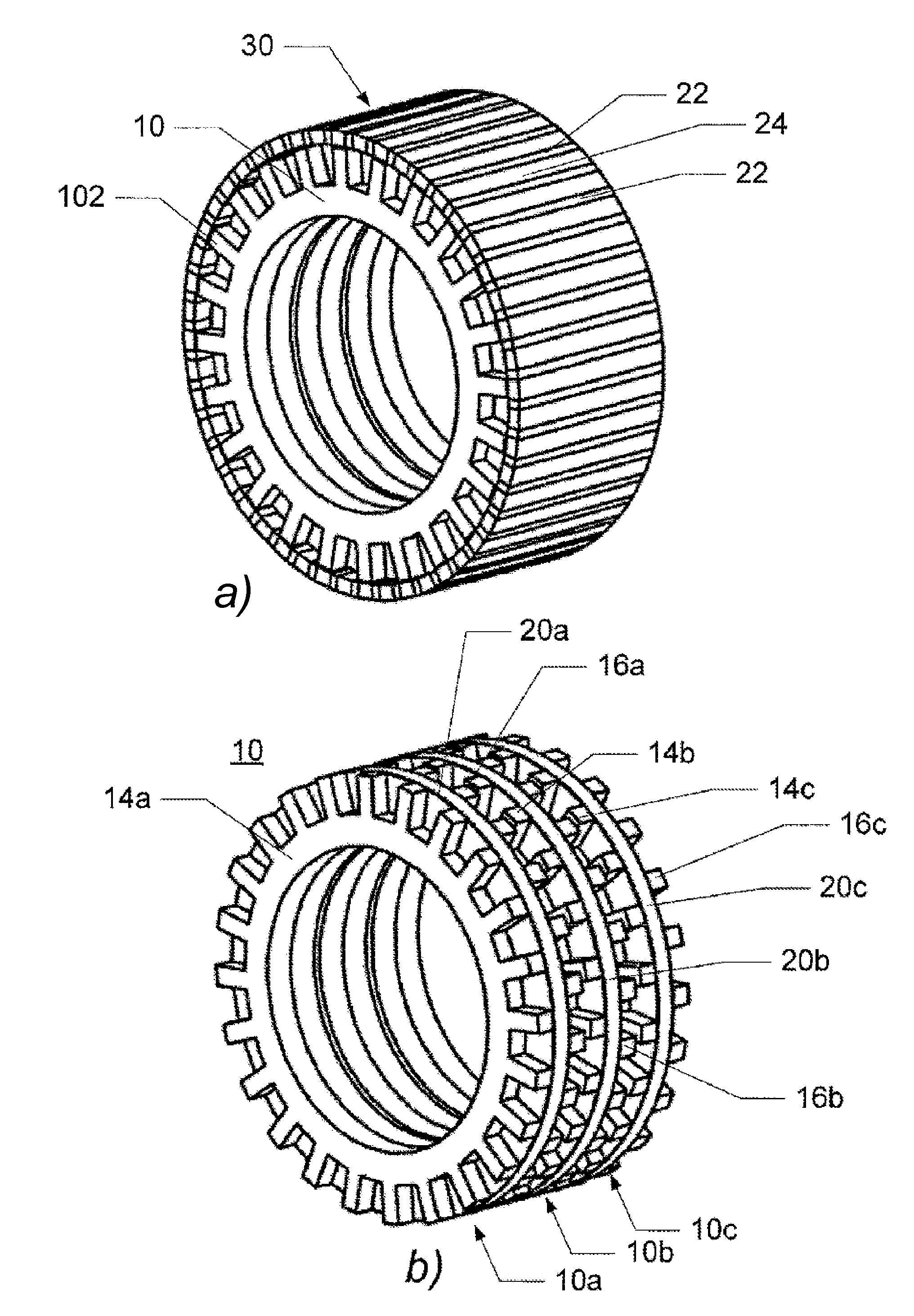
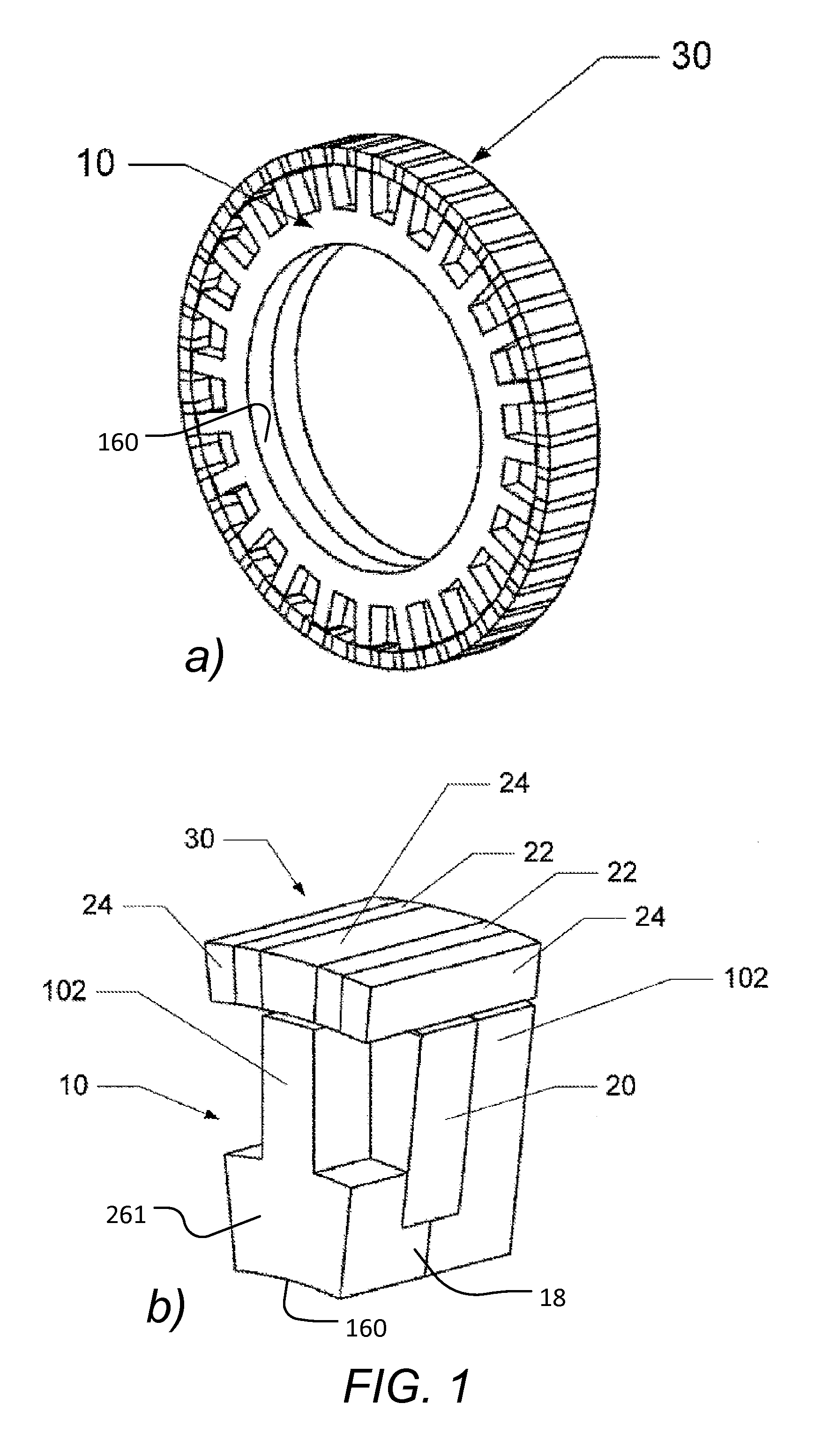
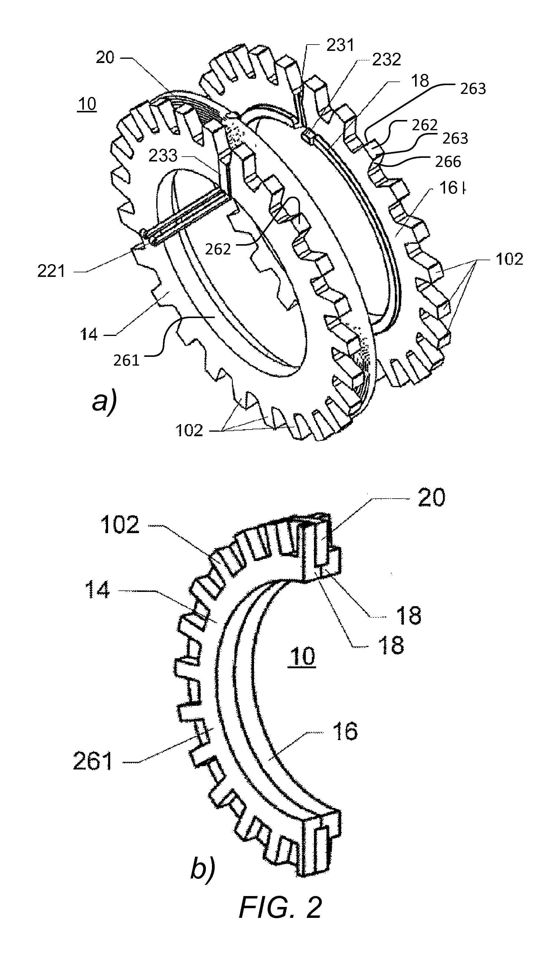
[0045]FIG. 1 illustrates an example of a modulated pole machine. In particular, FIG. 1 shows the active parts of a single phase, e.g. a one-phase machine or a phase of a multi-phase machine. FIG. 1a shows a perspective view of the active parts of the machine including a stator 10 and a rotor 30. FIG. 1b shows an enlarged view of a part of the machine. FIG. 2 illustrates an example of the stator 10 of the modulated pole machine of FIG. 1. In particular, FIG. 2a shows an exploded view of the stator 10, illustrating two stator core components 14, 16, and a coil 20. FIG. 2b shows a cut-view of the stator 10.

[0046]The machine comprises a stator 10 which comprises a central single coil 20 that magnetically feeds multiple teeth 102 formed by a soft magnetic stator core structure. While in other common electrical machine structures the coil ...


PUM


Abstract

A stator core component for a stator of a modulated pole machine, the modulated pole machine including the stator and a rotor, the stator and the rotor defining an air gap between respective interface surfaces of the rotor the stator for communicating magnetic flux between the stator and the rotor, wherein the stator core component includes an annular part from which a plurality of teeth extend in a radial direction towards the rotor, the teeth being arranged along a circumference of the annular part, each tooth having an interface surface facing the air gap and adapted to allow magnetic flux to communicate between the stator and the rotor via the air gap, the interface surface of each tooth defining a tooth span in the circumferential direction of the tooth.

Description

FIELD OF THE INVENTION[0001]This invention generally relates to modulated pole machines. More particularly, the invention relates to a stator for such a modulated pole machine.BACKGROUND OF THE INVENTION[0002]Over the years, electric machine designs such as modulated pole machines have attracted more and more interest. Electric machines using the principles of these machines were disclosed as early as about 1890 by W. M. Mordey and 1910 by Alexandersson and Fessenden. One of the most important reasons for the increasing interest is that the design enables a very high torque output in relation to, for instance, induction machines, switched reluctance machines and even permanent magnet brushless machines. Further, such machines are advantageous in that the coil is often easy to manufacture. However, one of the drawbacks of the design is that they are typically relatively expensive to manufacture.[0003]Stators of modulated pole electric machines generally use of a central single coil t...

Claims


Application Information

Patent Timeline
IPC IPC(8): H02K1/14H02K1/27H02K1/02
CPCH02K1/145H02K1/2786H02K1/02H02K21/227H02K1/2791
Inventor WASHINGTON, JAMIE
Owner HOGANAS AB
Why Eureka
Try Eureka