
A compensation method for dead zone effect of three-phase two-level inverter based on spwm technology

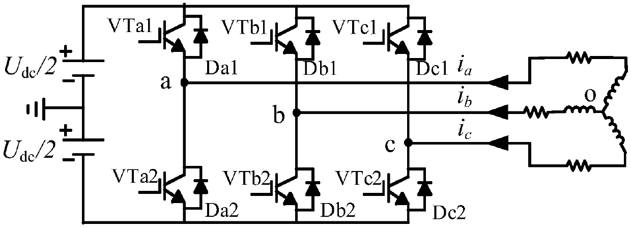
A technology of dead zone effect and compensation method, applied in the direction of electrical components, circuit devices, AC network circuits, etc., can solve the problems of inability to realize quantitative analysis of compensation effect, failure to obtain compensation effect, wrong compensation, etc., to achieve compensation of dead zone effect, Strong effectiveness and the effect of reducing the total harmonic content

Inactive Publication Date: 2018-07-20
SICHUAN UNIV
View PDF1 Cites 0 Cited by
  • Summary
  • Abstract
  • Description
  • Claims
  • Application Information

AI Technical Summary

Problems solved by technology

The switching tube conduction time compensation method, due to the estimated delay, often leads to wrong compensation, so that the ideal compensation effect cannot be obtained
The output voltage deviation compensation method cannot realize quantitative analysis of its compensation effect
Few studies have demonstrated the effectiveness and accuracy of compensation methods from the perspective of harmonic quantitative analysis

Method used


Image

  • A compensation method for dead zone effect of three-phase two-level inverter based on spwm technology
  • A compensation method for dead zone effect of three-phase two-level inverter based on spwm technology
  • A compensation method for dead zone effect of three-phase two-level inverter based on spwm technology

Examples


Embodiment

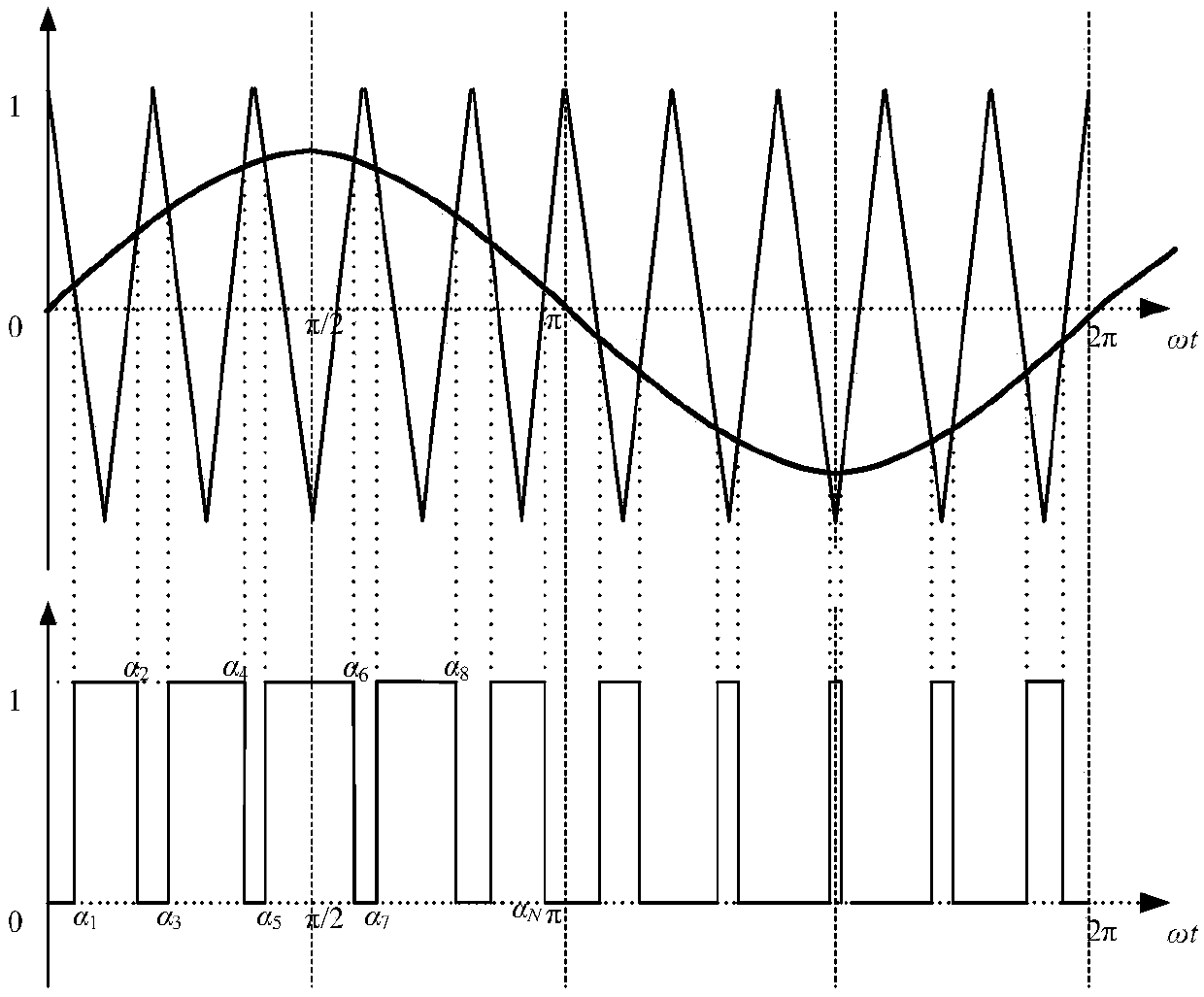
[0091] A typical two-level inverter is used to compare the simulation and theoretical calculations. The frequency of the sinusoidal modulation wave of the inverter is f=50Hz, and the triangular carrier frequency is f c =10kHz, DC side voltage is U dc =100V, modulation degree m=0.7, dead time T d =12.5μs, the dead zone compensation is T x =0.5*T d , T x =0.8*T d , T x =T d . The time-domain simulation model of the inverter is built on the Matlab / Simulink platform. When the amount of dead zone compensation is different, the ground phase voltage is calculated for no dead zone without compensation, dead zone without compensation, and dead zone with compensation. Leaf analysis and comparison ( Image 6 , Figure 7 , Figure 8 ).

[0092] Simulation Results and Analysis

[0093] This simulation test is to compare the dead zone effect compensation method of injecting compensation components into the inverter modulation signal with the results of no dead zone without comp...


PUM


Abstract

The invention discloses a three-phase two-electric-level inverter dead zone effect compensation method based on SPWM technology. The three-phase two-electric-level inverter dead zone effect compensation method comprises steps of injecting a compensation component in a modulation wave of an inverter, performing time compensation on conducting time of a switching tube which is used for determining output phase voltage, when phase current satisfies ia>0, increasing conducting time of a switching tube VTa2 determining output phase voltage to make the conducting time close to ideal conducting time of no dead zone in order to reduce waveform distortion, when phase current satisfied ia<0, increasing conducting time of a switching tube VTa1 determining output phase voltage to make the conducting time close to ideal conducting time of no dead zone in order to reduce waveform distortion, wherein a magnitude of a compensation component ud is determined by compensation time Tx which is set according to expectation and is obtained through performing quantitatively analyzing and calculating on harmonic wave before and after compensation. Targeting harmonic wave inhibition, the invention brings forward a dead zone effect compensation method for injecting the compensation component in a modulation signal of the inverter, can effectively compensate the dead zone effect, can reduce a total harmonic content of current and is high in efficiency and accuracy.

Description

technical field [0001] The invention relates to the technical field of converter control and modulation, in particular to a three-phase two-level inverter dead zone effect compensation method based on SPWM (sinusoidal pulse width modulation) technology. Background technique [0002] The dead zone compensation of PWM inverter is of great significance in improving the harmonic pollution and harmonic resonance problems of the inverter. The application of PWM technology makes the voltage source inverter have the advantages of simple circuit, high efficiency and fast dynamic response. However, the harmonic problem caused by the dead zone effect of the three-phase pulse width modulation voltage source inverter will also have an adverse effect on the grid-connected grid and loads, and may cause harmonic instability or harmonic resonance. Therefore, it is of great significance to study the compensation of the dead zone effect of the inverter. [0003] For the dead zone compensatio...

Claims


Application Information

Patent Timeline
Patent Type & Authority Patents(China)
IPC IPC(8): H02M7/483H02M7/5395H02J3/38H02M1/12H02P27/08
CPCH02J3/381H02M1/12H02M7/483H02M7/5395H02P27/085
Inventor 王顺亮焦宁刘天琪
Owner SICHUAN UNIV
Learn More