Self-Calibration of Source-Measure Unit via Capacitor

a capacitor and source-measure technology, applied in the direction of electronic circuit testing, measurement devices, instruments, etc., can solve the problems of high cost and complexity of self-calibration circuitry, 1 k resistor may yield poor results when calibrating the 10 a operating range, and complicated switching between resistors, so as to achieve the effect of maximum signal-to-noise ratio

Active Publication Date: 2015-06-18
NATIONAL INSTRUMENTS
View PDF1 Cites 6 Cited by
  • Summary
  • Abstract
  • Description
  • Claims
  • Application Information

AI Technical Summary

Benefits of technology

The patent describes a method for calibrating and operating a source-measure unit (SMU) by applying an excitation signal to a capacitor. The excitation signal has a specific amplitude and operating frequency, which can be set to maximize a signal-to-noise ratio. The resulting signal is used to calibrate the SMU. The technical effect of this method is an improved accuracy and reliability in the calibration of the SMU, which can lead to more accurate and reliable measurements in various fields such as electronics and optics.

Problems solved by technology

In such instances, the self-calibration circuitry may become expensive and complex if the SMU includes many operating ranges or if the operating ranges span a large dynamic range.
However, the 1 kΩ resistor may yield poor results when calibrating the 10 μA operating range because only 10 mili-volts (mV), or 1% of the full-scale range of the 1V operating range, would be required to achieve full-scale current on the 10 μA operating range.
Additionally, switching between the resistors may be complicated by the need to avoid introducing errors from the switch resistance.

Method used


Image

  • Self-Calibration of Source-Measure Unit via Capacitor
  • Self-Calibration of Source-Measure Unit via Capacitor
  • Self-Calibration of Source-Measure Unit via Capacitor

Examples


Embodiment Construction

Incorporation by Reference

[0042]The following reference is hereby incorporated by reference in its entirety as though fully and completely set forth herein:

[0043]U.S. Pat. No. 7,903,008 titled “Source-Measure Unit Based on Digital Control Loop,” issued on Nov. 6, 2008.

TERMS

[0044]The following is a glossary of terms used in the present application:

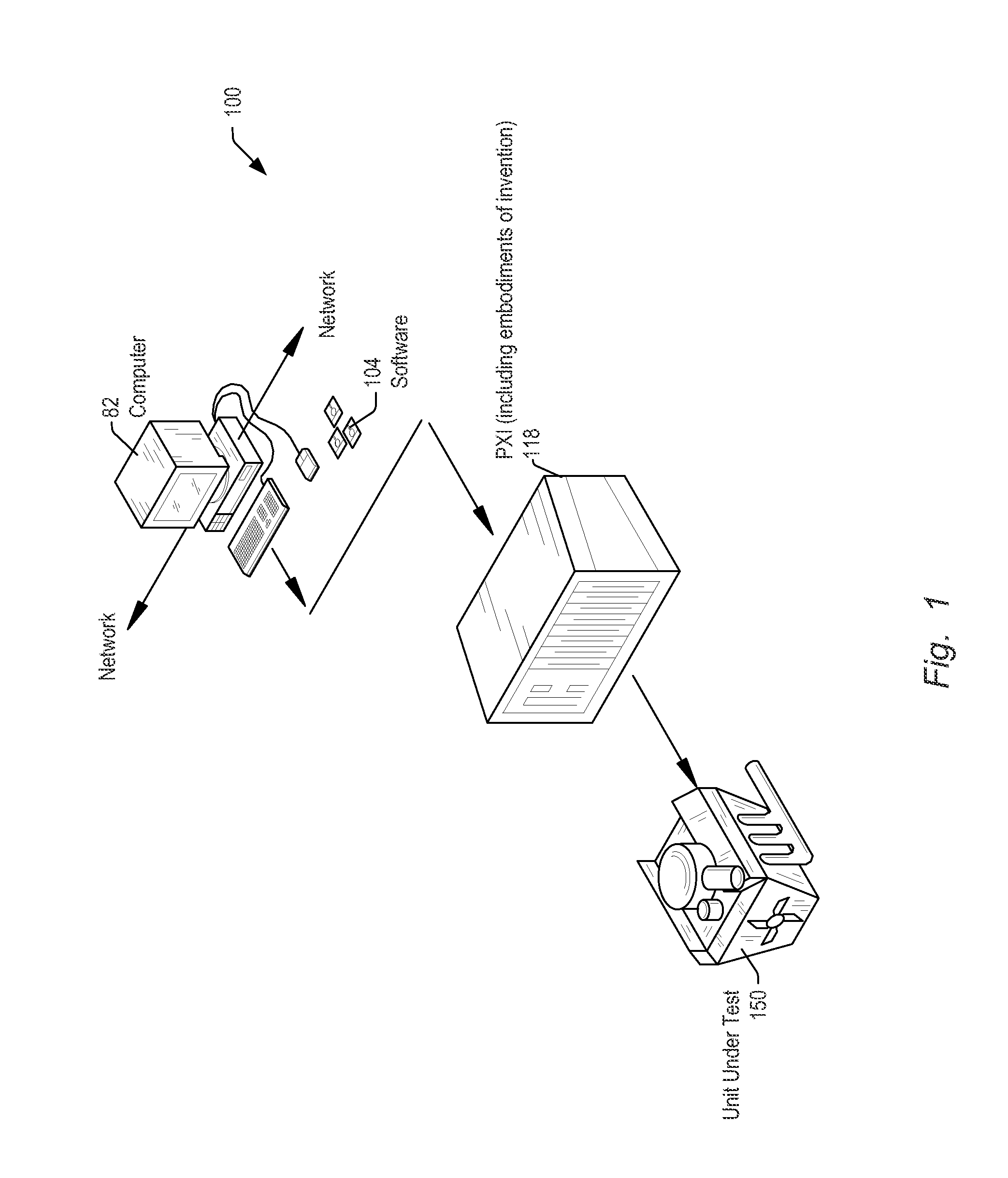
[0045]Memory Medium—Any of various types of non-transitory computer accessible memory devices or storage devices. The term “memory medium” is intended to include an installation medium, e.g., a CD-ROM, floppy disks 104, or tape device; a computer system memory or random access memory such as DRAM, DDR RAM, SRAM, EDO RAM, Rambus RAM, etc.; a non-volatile memory such as a Flash, magnetic media, e.g., a hard drive, or optical storage; registers, or other similar types of memory elements, etc. The memory medium may comprise other types of non-transitory memory as well or combinations thereof. In addition, the memory medium may be located in a f...


PUM


Abstract

Systems and methods for calibration and operation of a source-measure unit (SMU). The system may include a functional unit and output terminals coupled to the functional unit. An excitation signal may be applied to a capacitor by the SMU. The capacitor may be included in a calibration circuit. The method may include obtaining one or more of a current calibration coefficient (CCC) or a voltage calibration coefficient (VCC). The CCC may correspond to a current-range setting and the VCC may correspond to a voltage-range setting. The CCC may be obtained from a value of a first current and a value of a second current developed in the capacitor responsive to the excitation signal. The VCC may be obtained from a value of a first voltage and a value of a second voltage developed across the capacitor responsive to the excitation signal.

Description

FIELD OF THE INVENTION[0001]The present invention relates generally to measurement and data acquisition systems and, more particularly, to the calibration and operation of source-measure units.DESCRIPTION OF THE RELATED ART[0002]Scientists and engineers often use measurement systems to perform a variety of functions, including measurement of a physical phenomenon, a unit under test (UUT) or device under test (DUT), test and analysis of physical phenomena, process monitoring and control, control of mechanical or electrical machinery, data logging, laboratory research, and analytical chemistry, to name a few examples.[0003]A typical measurement system comprises a computer system, which commonly features a measurement device, or measurement hardware. The measurement device may be a computer-based instrument, a data acquisition device or board, a programmable logic device (PLD), an actuator, or other type of device for acquiring or generating data. The measurement device may be a card o...

Claims


Application Information

Patent Timeline
IPC IPC(8): G01R35/00G01R31/28
CPCG01R31/28G01R35/005
Inventor REGIER, CHRISTOPHER G.LIMON, PABLO
Owner NATIONAL INSTRUMENTS
Why Eureka
Try Eureka