
Infrared detection device

a detection device and infrared technology, applied in the direction of optical radiation measurement, instruments, material analysis, etc., can solve the problems of pyroelectric detection devices, inability to accurately sense the temperature distribution in space, and inability to minutely sense the two-dimensional behavior of people, so as to prevent warpage and destruction of the sensing layer, high infrared detection, and high heat insulation

Inactive Publication Date: 2015-06-18
PANASONIC INTELLECTUAL PROPERTY MANAGEMENT CO LTD
View PDF40 Cites 4 Cited by
  • Summary
  • Abstract
  • Description
  • Claims
  • Application Information

AI Technical Summary

Benefits of technology

The patent text describes a method of improving infrared detection by using a substrate with a thermal expansion coefficient larger than the sensing layer, which allows for a compressive stress to be applied to the sensing layer. Additionally, an intermediate layer with a decreased thermal expansion coefficient prevents warping and destruction of the sensing layer in devices that have thin legs and high heat insulation. This results in a higher infrared detection device.

Problems solved by technology

A previous pyroelectric detecting device, however, is almost unable to minutely sense two-dimensional behavior of a person or to accurately sense the temperature distribution in a space.

Method used


Image

  • Infrared detection device
  • Infrared detection device
  • Infrared detection device

Examples


Embodiment Construction

[0025]Prior to the description of an embodiment of the present invention, a description is made of some disadvantages in the conventional infrared detection device. The array-type infrared detection device shown in FIG. 6 includes substrate 200 made of silicon with a smaller linear thermal expansion coefficient, and pyroelectric layers 213 and 223 provided on substrate 200 and made of PZT with a larger linear thermal expansion coefficient. Accordingly, the detection device has low pyroelectric characteristics. Meanwhile, all of the four sides of pyroelectric layer 213 are in contact with substrate 200 made of silicon with very high heat conductivity via film 201. Accordingly, heat generated in pyroelectric layer 213 by receiving infrared rays easily escapes.

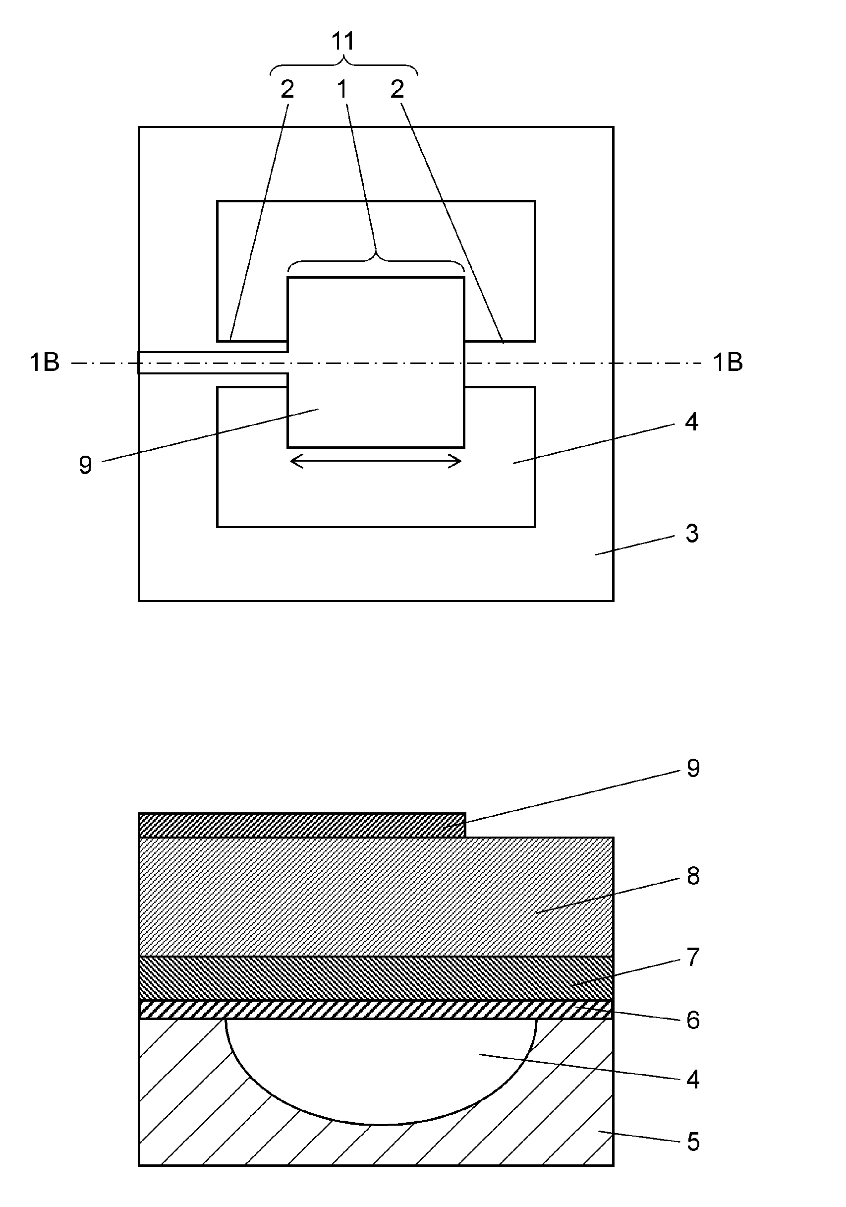
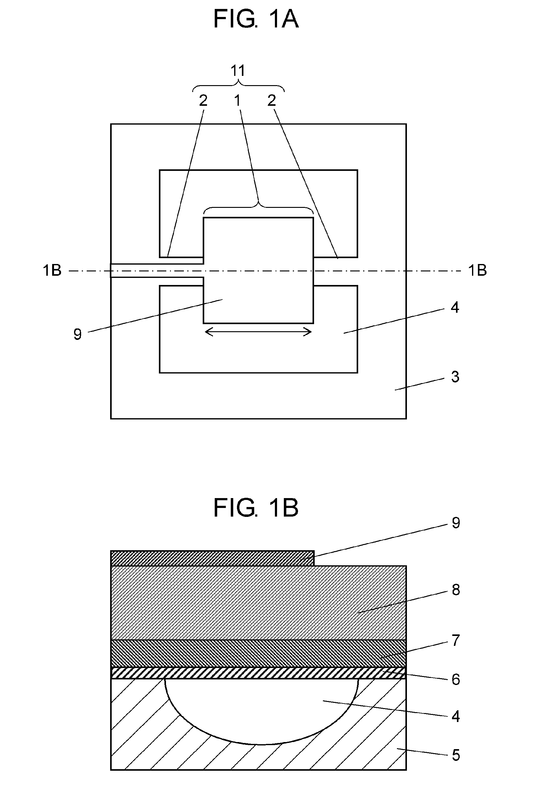
[0026]Hereinafter, a description is made of the embodiment using the related drawings. FIG. 1A is a top view of the outline structure of an infrared detection device according to the embodiment of the present invention. FIG. 1B i...


PUM


Abstract

An infrared detection device includes a substrate and a heat-type light sensing element. The substrate has a recess, and a frame positioned around the recess. The heat-type light sensing element has a leg and a sensing unit, and the leg is connected onto the frame so that the sensing unit is positioned over the recess. The heat-type light sensing element includes an intermediate layer provided on the substrate, a first electrode layer provided on the intermediate layer, a sensing layer provided on the first electrode layer, and a second electrode layer provided on the sensing layer. The substrate has a linear thermal expansion coefficient larger than that of the sensing layer. The intermediate layer has a linear thermal expansion coefficient decreasing toward the first electrode layer from the substrate.

Description

TECHNICAL FIELD[0001]The present invention relates to an infrared detection device determining electrical properties that change according to temperature rise caused by receiving infrared rays and to a method of producing the infrared detection device.BACKGROUND ART[0002]As a sensor device that senses temperature in a noncontact manner, an infrared detection device that is a heat-type using infrared rays has been devised up to now. Examples of a heat-type infrared detection device include a pyroelectric detecting device, resistance bolometer detecting device, and thermopile detecting device. A pyroelectric detecting device employs a pyroelectric material that generates electric charge on its surface due to temperature change. A resistance bolometer detecting device employs a resistance bolometer material that changes its resistance value due to temperature change. A thermopile detecting device uses the Seebeck effect in which a thermoelectromotive force is generated due to temperatu...

Claims


Application Information

Patent Timeline
Patent Type & Authority Applications(United States)
IPC IPC(8): G01J5/34
CPCG01J5/34G01J5/046G01J5/023G01J5/024G01J2005/345G01J5/0853H10N15/10
Inventor NODA, TOSHINARI
Owner PANASONIC INTELLECTUAL PROPERTY MANAGEMENT CO LTD
Learn More