Ignition coil and method of assembly

a technology of ignition coil and coil body, which is applied in the direction of inductance, chemistry apparatus and processes, and other domestic objects, can solve the problems of complex and costly connection between the low voltage end and the high-voltage end of the secondary winding to their respective terminals, and add a resistor to the system

Active Publication Date: 2015-06-18
DELPHI TECH IP LTD
View PDF1 Cites 8 Cited by
  • Summary
  • Abstract
  • Description
  • Claims
  • Application Information

AI Technical Summary

Benefits of technology

[0009]The ignition coil and method of assembling the ignition coil eliminates the need for processing steps for pr

Problems solved by technology

Connecting the low voltage end and the high-voltage end of the secondary winding to their respectiv

Method used


Image

  • Ignition coil and method of assembly
  • Ignition coil and method of assembly
  • Ignition coil and method of assembly

Examples


Embodiment Construction

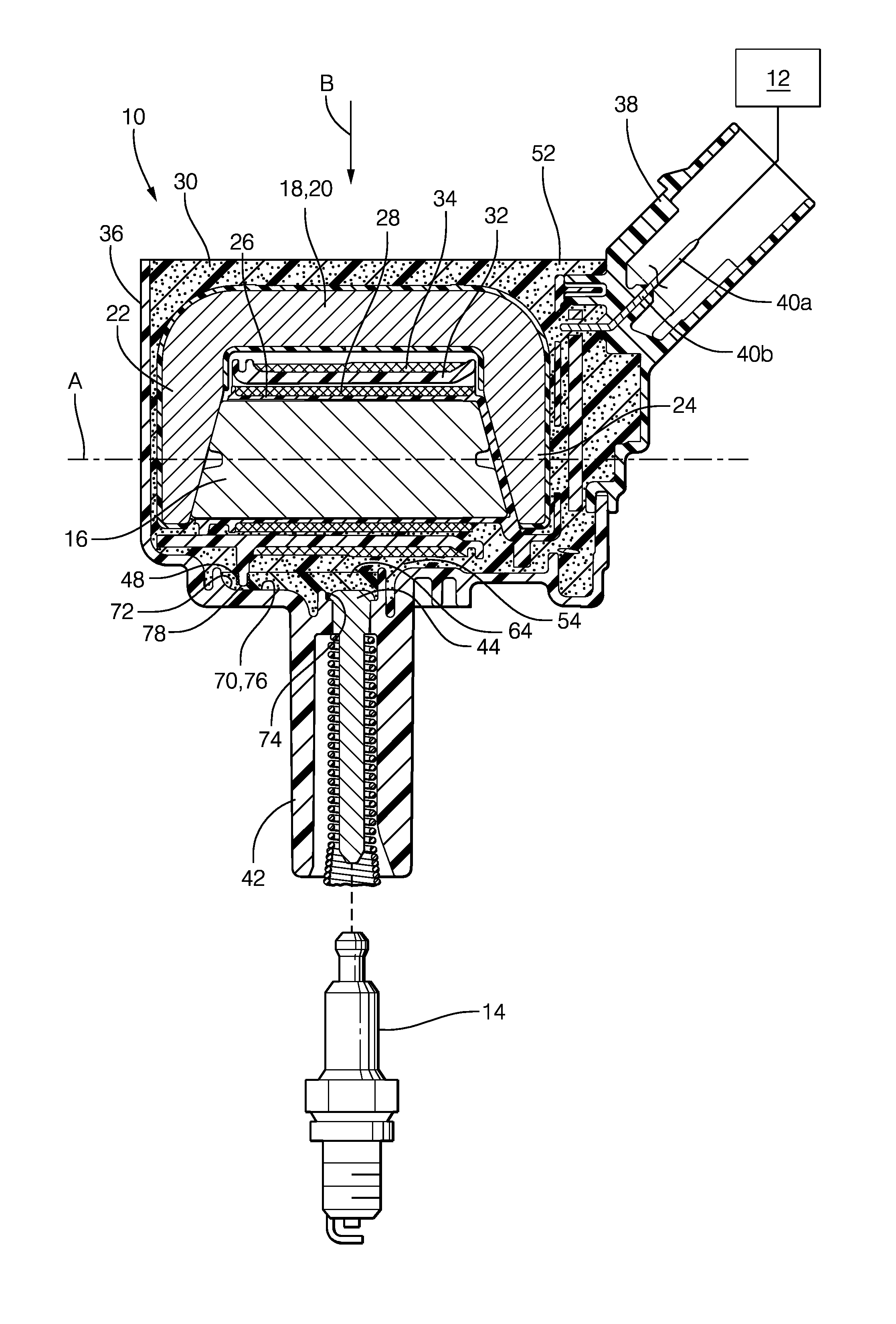
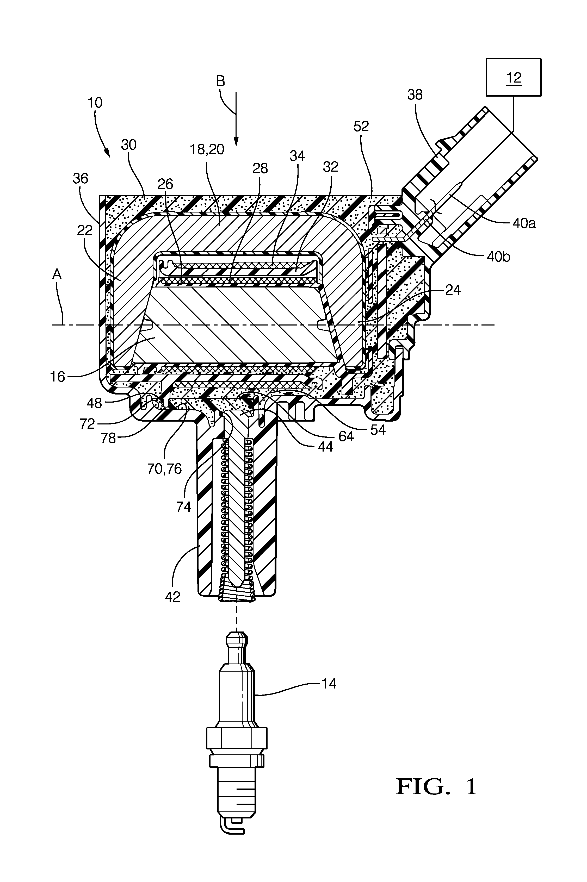
[0017]Reference will first be made to FIGS. 1 and 2 which show simplified cross-section views of an ignition coil 10 where FIGS. 1 and 2 are sectioned by parallel planes. Ignition coil 10 may be controlled by a control unit 12 or the like. Ignition coil 10 is configured for connection to a spark plug 14 that is in threaded engagement with a spark plug opening (not shown) in an internal combustion engine (also not shown). Ignition coil 10 is configured to deliver a high-voltage spark-generating current to spark plug 14, as shown. Generally, overall spark timing (dwell control) and the like is provided by control unit 12. One ignition coil 10 may be provided per spark plug 14.

[0018]Ignition coil 10 may include a magnetically-permeable core 16, a magnetically-permeable structure 18, hereinafter referred to as high-permeance structure 18, configured to provide a high permeance magnetic return path which has a base section 20 and a pair of legs 22 and 24, a primary winding spool 26, a pr...


PUM

PropertyMeasurementUnit
Electrical resistanceaaaaaaaaaa
Electrical conductivityaaaaaaaaaa

Abstract

An ignition coil for delivering a spark-generating current to a spark plug includes a magnetically-permeable core; a primary winding disposed outward of the core; and a secondary winding disposed outward of the primary winding and inductively coupled to the primary winding. The secondary winding terminates at one end thereof in a low-voltage end and terminates at another end thereof in a high-voltage end. At least one of the low-voltage end of the secondary winding and the high-voltage end of the secondary winding is electrically connected directly to a terminal through an electrically conductive polymer.

Description

CROSS-REFERENCE TO RELATED APPLICATIONS[0001]This patent application claims the benefit of U.S. provisional patent application Ser. No. 61 / 917,588 filed on Dec. 18, 2013, the disclosure of which is hereby incorporated by reference in its entirety.TECHNICAL FIELD OF INVENTION[0002]The present invention relates to an ignition coil for developing a spark-generating current that is applied to one or more spark plugs of an internal combustion engine.BACKGROUND OF INVENTION[0003]Ignition coils are known for use in connection with an internal combustion engine such as an automobile engine. Ignition coils typically include a core around which is wound a primary winding. A secondary winding is wound around a secondary winding spool to surround the primary winding such that a high voltage is induced on the secondary winding when an electric current applied to the primary winding is stopped. One end of the secondary winding is a low voltage end which is connected to a ground terminal while the...

Claims


Application Information

Patent Timeline
IPC IPC(8): F02P1/08B32B37/14B32B37/12H01F41/04
CPCF02P1/08H01F41/04B32B2457/00B32B37/1284B32B2037/1246B32B37/142F02P3/02H01F38/12H01F27/04B32B37/12
Inventor SKINNER, ALBERT A.LEVERS, JR., HARRY O.SKINNER, MARY A.MEZA, MARCO
Owner DELPHI TECH IP LTD
Why Eureka
Try Eureka