Heat exchanger

Active Publication Date: 2015-06-11
MAHLE INT GMBH
View PDF10 Cites 2 Cited by
  • Summary
  • Abstract
  • Description
  • Claims
  • Application Information

AI Technical Summary

Benefits of technology

The present invention aims to provide a heat exchanger which can relieve stresses in the transitional region between high-temperature and low-temperature chambers without increasing production costs. The invention achieves this by using stress decoupling devices, such as slots and controlled attenuation of stiffness, to prevent stresses arising during the flow of a coolant from the high-temperature chamber into the low-temperature chamber. The formation of a stress decoupling device requires little effort and reduces heat exchanger production costs. Additionally, the invention uses a first stress decoupling device in the bottom and / or a second stress decoupling device in the area of the partition wall in a collecting tank to compensate for uncontrolled thermal loads caused by tube expansions. Despite the use of such stress decoupling devices, the heat exchanger always still has a sufficient pressure resistance to prevent medium leakage outside.

Problems solved by technology

As a result, defects can arise in the area of the partition walls, which occur, for example, as cracks in the tubes.
However, conventional heat exchangers comprise a more complex structure increasing the assembly effort and thereby the production costs of the heat exchanger.
Moreover, this type of design does not guarantee the complete prevention of damage to the tubes.
The heat exchangers do not allow a sufficient temperature expansion compensation, because the cover of the heat exchanger is made of a continuous sheet profile.

Method used


Image

  • Heat exchanger
  • Heat exchanger
  • Heat exchanger

Examples


Embodiment Construction

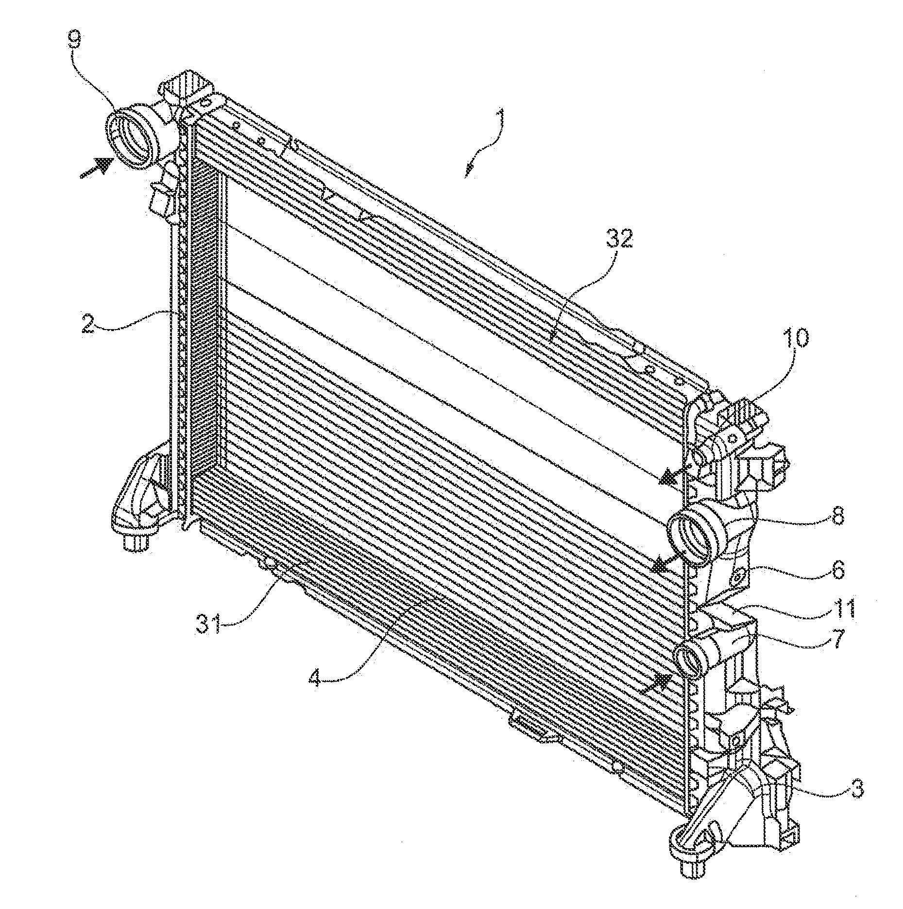
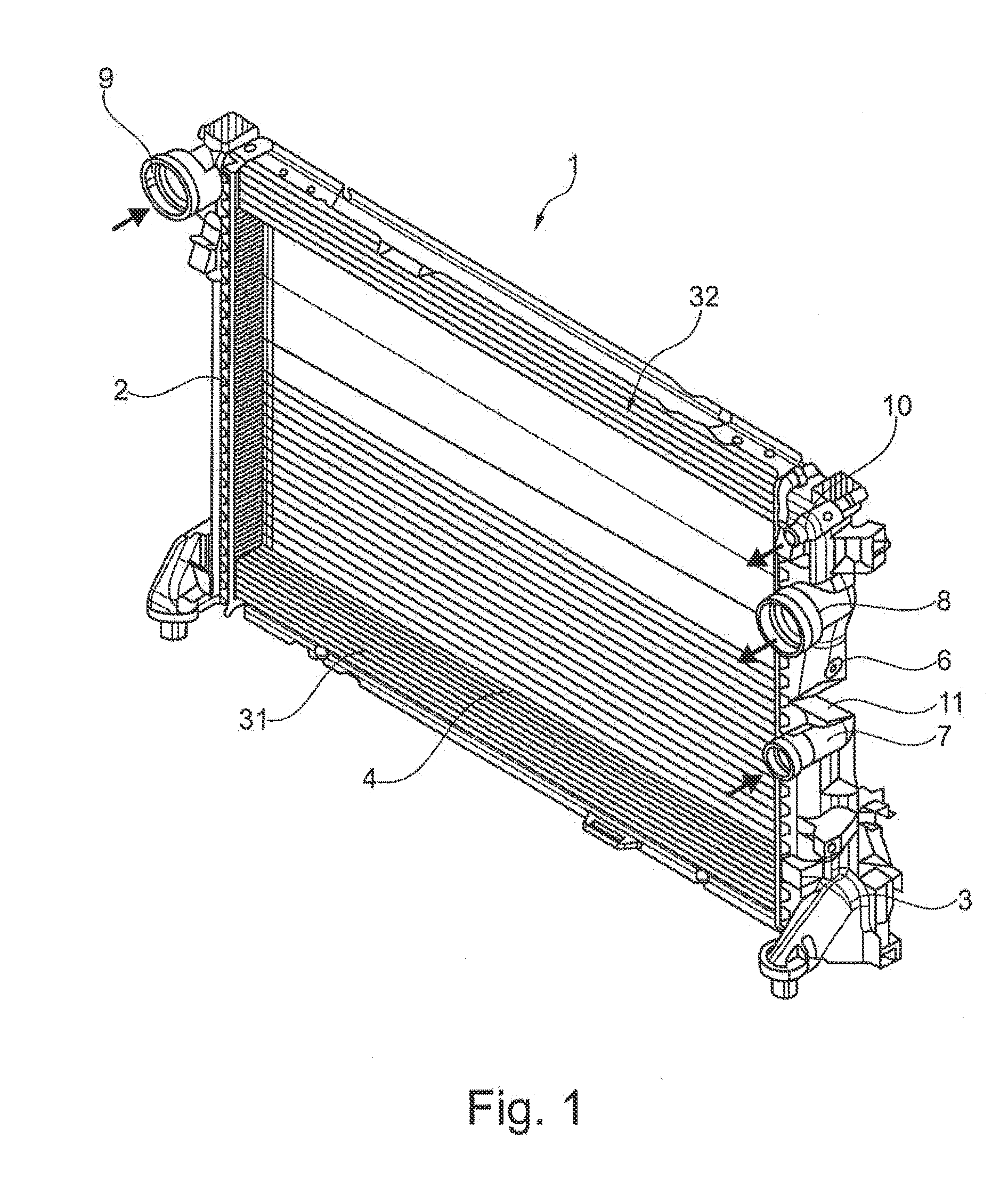
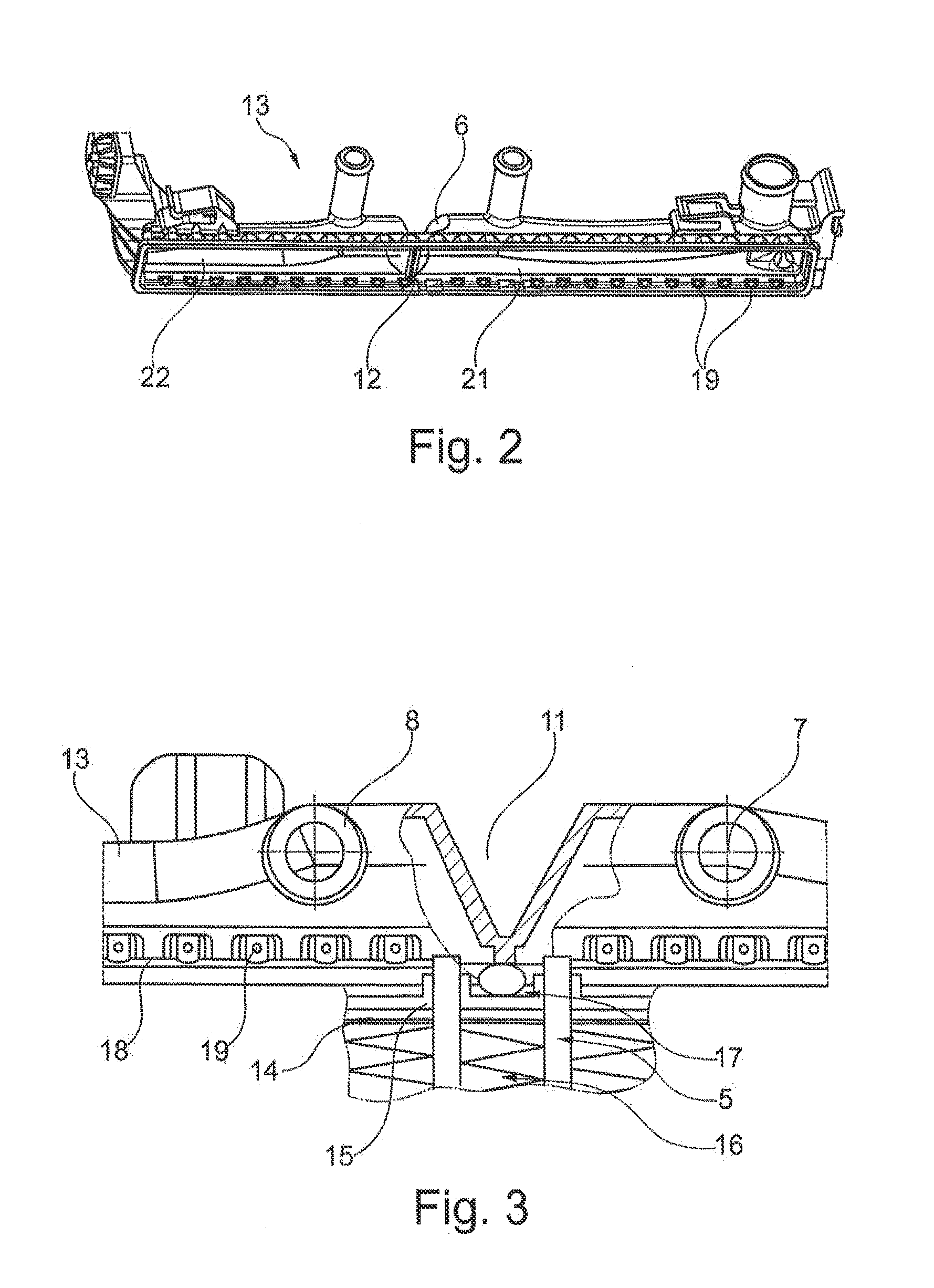
[0029]FIG. 1 shows a first exemplary embodiment of heat exchanger 1 of the invention. Heat exchanger 1 has two collecting tanks 2, 3, between which a tube-fin block 4 is disposed. Tubes 5 formed within tube-fin block 4 engage with their respective ends in collecting tanks 2 or 3. Collecting tank 3 has a recess 6, to which in the interior a partition wall 12 attaches, which divides collecting tank 3 into a high-temperature region 31 and a low-temperature region 32. This means that the illustrated heat exchanger 1 has a main circuit, which is realized by high-temperature region 31, and an integrated auxiliary circuit, which is formed by low-temperature region 32. Partition wall 12 in this case prevents the fluids to be cooled from intermixing within collecting tanks 2 and 3. High-temperature region 31 in this case has a medium supply connector 7 and a medium outlet connector 8. Low-temperature region 32 also comprises a medium supply connector 9 and a medium outlet connector 10, where...


PUM


Abstract

A heat exchanger having a tube-fin block that is closed by two collecting tanks, whereby the ends of the tubes engage in a bottom of the particular collecting tank and the bottom is closed with a cover. A partition wall secured to the cover is formed transverse to a longitudinal extension of the collecting tank and divides an interior space of the collecting tank into two subchambers. The heat exchanger, which prevents great structural changes for compensating temperature-induced stresses, a first stress decoupling device is formed in the bottom and / or a second stress decoupling device in the area of the partition wall in the cover of at least one collecting tank.

Description

[0001]This nonprovisional application claims priority to German Patent Application No. DE 10 2013 225 326.5, which was filed in Germany on Dec. 9, 2013, and which is herein incorporated by reference.BACKGROUND OF THE INVENTION[0002]1. Field of the Invention[0003]The present invention relates to a heat exchanger.[0004]2. Description of the Background Art[0005]DE 10 2005 031 475 A1 discloses a heat exchanger which has a tube-fin block closed on both sides by a collecting box. For receiving a coolant each collecting box has two side walls, two end walls, a cover, and a bottom arranged opposite to the cover. The bottom thereby comprises one or more openings for receiving tubes of the tube-fin block. The cover has a recess into which a partition wall extends dividing the interior space of the collecting tank into two subchambers.[0006]In the conventional are, if one of two subchambers is formed as a high-temperature chamber and the other of the two chambers as a low-temperature chamber, ...

Claims


Application Information

Patent Timeline
IPC IPC(8): F28F1/10
CPCF28F1/10F28F9/0209F28F9/0224F28D1/0443F28F2265/26F28F9/0202F28F2270/00
Inventor GHIANI, FRANCOSTRESE, THOMASROUHANA, HICHAMKRISA, ROLANDNGUYEN, CHI-DUCHELMS, WERNERHEINE, REINHARD
Owner MAHLE INT GMBH
Why Eureka
Try Eureka