Eureka AIR delivers breakthrough ideas for toughest innovation challenges, trusted by R&D personnel around the world.

Apparatus and method for controlling a suspended state

a technology of apparatus and state, applied in the field of controlling a suspended state, can solve the problems of device being released from the suspended state inadvertently, loss of the benefit loss of the suspended state, so as to reduce processing and/or power consumption

Active Publication Date: 2015-06-04
SONY CORP
View PDF29 Cites 23 Cited by
  • Summary
  • Abstract
  • Description
  • Claims
  • Application Information

AI Technical Summary

Benefits of technology

The patent text describes a technology that prevents a device from accidentally releasing a stand-by or suspended state, which could result in unnecessary power consumption and unintended processing. The device uses a proximity sensor to detect if an object is close to it and, based on that information, determines if it is in a stand-by state or if it's being used. If it's being used, the device will continue to perform its normal functions. However, if it's in stand-by state, the device will reduce its power consumption and processing capabilities to protect the user's privacy or to prevent accidental clicks. This technology ensures that the device is always aware of its surroundings and ensures that it can react quickly to user input while conserving power.

Problems solved by technology

In cases where the suspended state may be released in response to detecting an input operation other than a physical button manipulation, a situation arises where the device may be released from the suspended state inadvertently, without the knowledge of the user.
For example, a touch operation may be detected when the terminal device is stored in a user's pocket, which may result in the suspended state being released when such an action is not desired.
Therefore, in these circumstances, the benefit of the suspended state is lost due to the unnecessary power consumption and unintended processing that results from an inadvertent release of the suspended state.

Method used


Image

  • Apparatus and method for controlling a suspended state
  • Apparatus and method for controlling a suspended state
  • Apparatus and method for controlling a suspended state

Examples


Embodiment Construction

[0033]Referring now to the drawings, wherein like reference numerals designate identical or corresponding parts throughout the several views.

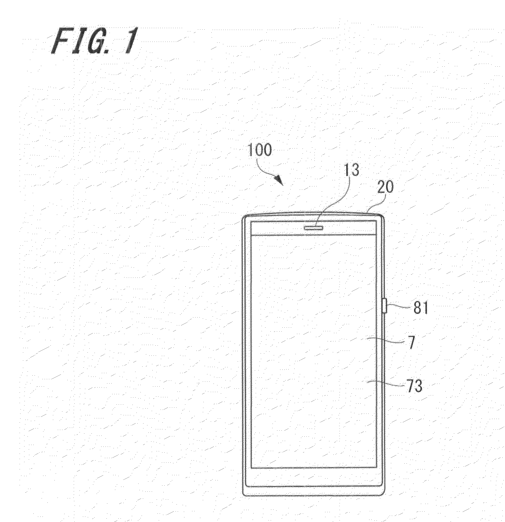
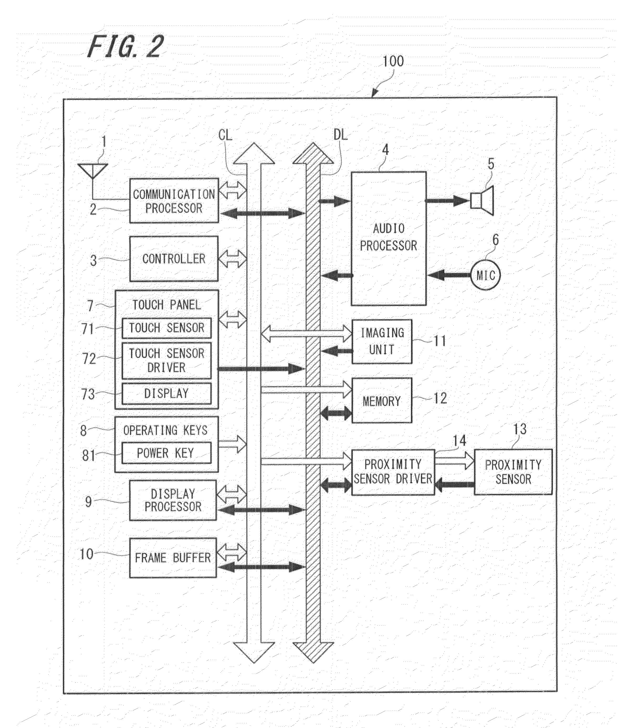
[0034]Referring first to FIG. 1, FIG. 1 illustrates a non-limiting example of a terminal device external structure, according to certain embodiments. Terminal device 100 illustrated in FIG. 1 includes a protective case 20 surrounding a display 73. The display 73 is included on a frontal surface of the terminal device100 and, in certain embodiments, may be formed integrally with a touch panel 7. The touch panel 7 may, in certain embodiments, including one or more touch sensors for detecting a touch operation on an operating surface of the display 73. Aspects of detecting a touch operation on the display 73 will be discussed later in greater detail.

[0035]The exemplary terminal device 100 of FIG. 1 includes a power key 81 disposed along an edge of the terminal device 100. In certain embodiments, in addition to providing a mechanism for cycling pow...


PUM


Abstract

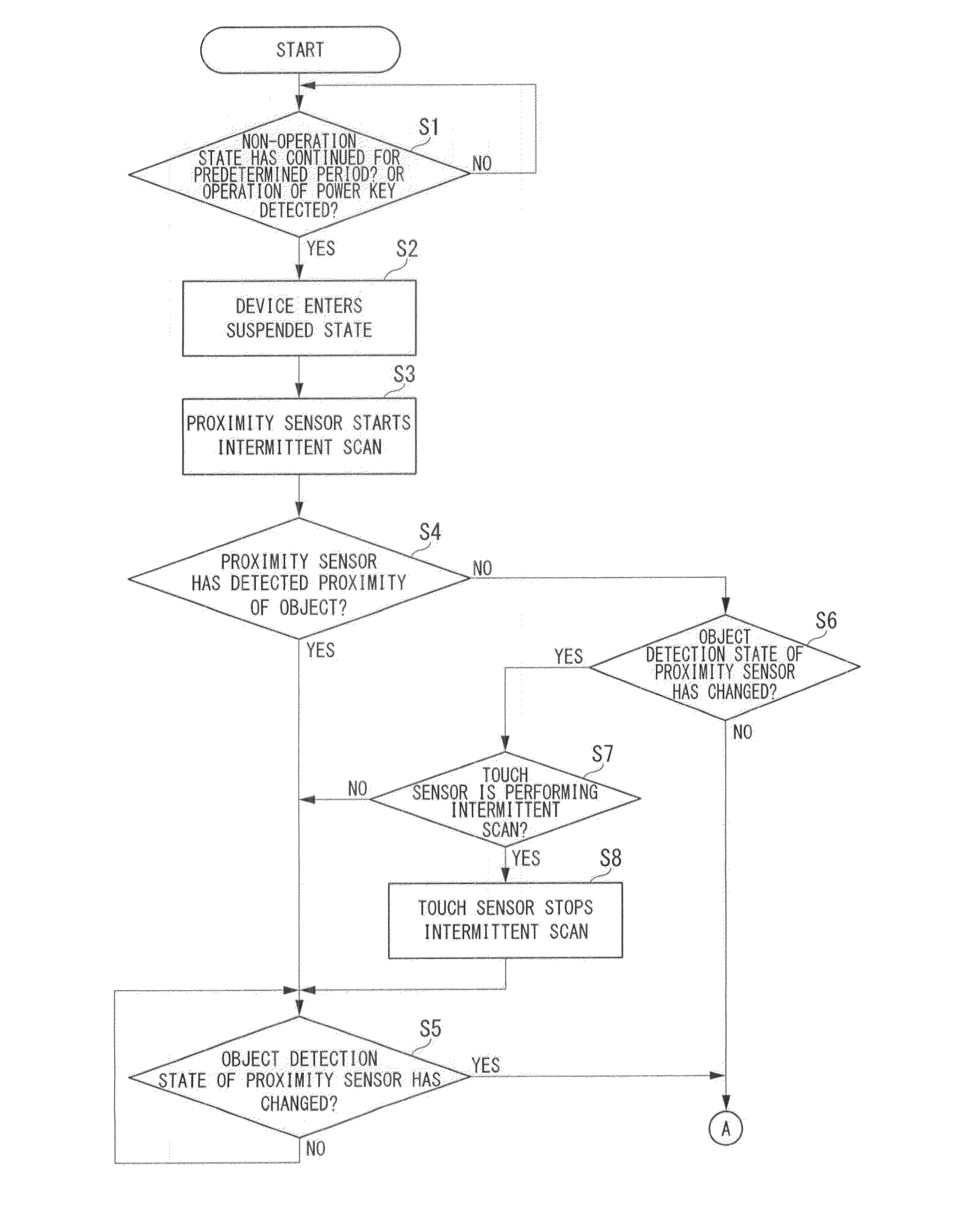
A device includes a proximity sensor configured to detect when an object is within a predetermined proximity range of the device, and input detection circuitry configured to detect when an input operation is performed on the device. The terminal device includes control circuitry configured to determine a proximity detection state of the device, wherein an object detection state corresponds to a proximity state in which the object is detected within the predetermined proximity range, and an object non-detection state corresponds to a proximity state in which the object is not detected within the predetermined proximity range; control a suspended state of the device, wherein the suspended state is a state of reduced processing and / or power consumption; and control the input detection circuitry such that, when the device is in the suspended state and in the object detection state, the input detection circuitry stops input operation detection processing.

Description

BACKGROUND[0001]1. Technical Field[0002]The present disclosure relates to controlling a suspended state of a terminal device, such as a mobile phone, a smart phone, a tablet device, or the like.[0003]2. Description of Related Art[0004]Terminal devices may include a processor configured to place the terminal device in a suspended state to preclude unnecessary consumption of power resources while the device is not in use. Some terminal devices may include external buttons, and a signal may be generated to release the terminal device from the suspended state when an external button operation is detected (e.g., pressing a power key). Other terminal device processors may be configured to release the device from the suspended state based on inputs other than physical button operations. For example, a touch operation performed on a surface of a touch panel display included in the terminal device may be detected and in response, a signal may be generated to release the device from the suspe...

Claims


Application Information

Patent Timeline
IPC IPC(8): G06F1/32
CPCG06F1/32G06F1/3206G06F1/3262G06F1/3265G06F3/0488Y02D10/00G06F1/3203
Inventor TOKUTAKE, KENJI
Owner SONY CORP
Why Eureka
Eureka Blog
Learn More