
Failure recovery system and method of creating the failure recovery system

a failure recovery and failure recovery technology, applied in the field of failure recovery systems, can solve the problems of failure recovery not being carried out on the plural main system vms, affecting the performance before and after, and the delay in the start time of the communication service, so as to reduce the amount of physical resources

Inactive Publication Date: 2015-05-28
HITACHI LTD
View PDF7 Cites 30 Cited by
  • Summary
  • Abstract
  • Description
  • Claims
  • Application Information

AI Technical Summary

Benefits of technology

The patent aims to provide a failure recovery system that reduces the amount of physical resources used by the standby system and recovers the main system and plural main system VMs quickly when failure occurs. The goal is to improve the performance and efficiency of cloud computing and other IT infrastructure technologies. A separate physical server may be needed for failure recovery, and the invention proposes a method to reduce the impact on the standby system.

Problems solved by technology

However, because there is a need to restart the VM of the main system in the failure, a communication interruption time occurs in a start time of the VM, there arises such a problem that a restart time of the communication service is delayed.
Therefore, when this redundant configuration is used, there is a need to ensure the physical resources taking both of the main system VM and the standby system VM into account, which is problematic.
However, when the physical resources to be allocated to the standby system VM are simply set on the basis of the physical resources allocated to the plural main system VMs, the amount of physical resources allocated to a certain main system VM has the potential to be different from the amount of physical resources allocated to the standby system VM, which may greatly affect the performances before and after the failure.
Also, because the number of main system VMs is different from the number of standby system VMs, failure recovery may not be conducted on the plural main system VMs.
Therefore, it is difficult to effectively provide the advantages of both those techniques, which is problematic.
However, there is a possibility that the failure recovery is not rapidly conducted on the plural main system VMs, and the physical server to which the main system VM subjected to the failure recovery is shifted is required, which are problematic.

Method used


Image

  • Failure recovery system and method of creating the failure recovery system
  • Failure recovery system and method of creating the failure recovery system
  • Failure recovery system and method of creating the failure recovery system

Examples


Embodiment Construction

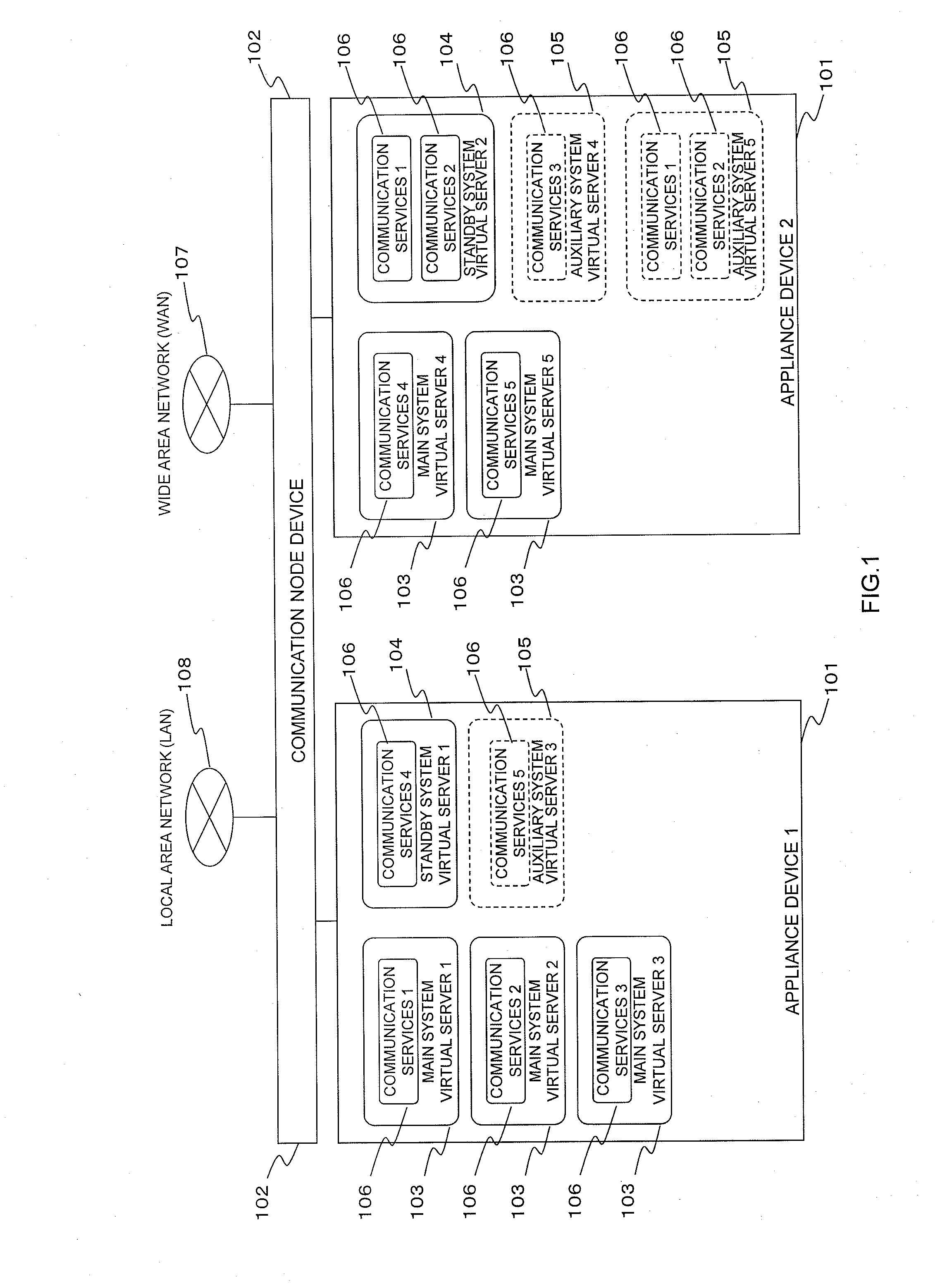
[0038]First, an outline of an embodiment will be described. A common standby system VM is produced on the basis of a configuration of a main system VM that runs a communication service. In this example, it is assumed that the configuration of the main system VM and the amount of physical resources to be allocated are patterned and provided, and the environment is created in the common standby system VM according to the configuration of the standby system VM and the amount of physical resources. Therefore, the environment such as a redundant configuration of N+M in which when N (N is a natural number of 2 or more) main system VMs are provided, M (M is a natural number of 1 or more) standby system VMs are prepared is created.

[0039]Subsequently, a power supply control of the related standby system VM is conducted according to an operating state such as a CPU utilization ratio of the respective main system VMs, or event information such as a configuration change of the main system VMs. ...


PUM


Abstract

When detecting the configuration change or the operating state of a virtual machine of the main system, a VM management unit changes a value of a determination index of the virtual machine, and selects a virtual machine of the standby system / auxiliary system used for failure recovery of the virtual machine of the main system on the basis of a value of the determination index. A pattern generation unit provides the virtual machine of the standby system / auxiliary system selected by the VM management unit.

Description

CLAIM OF PRIORITY[0001]The present application claims priority from Japanese patent application JP 2013-244190 filed on Nov. 26, 2013, the content of which is hereby incorporated by reference into this application.BACKGROUND OF THE INVENTION[0002]1. Field of the Invention[0003]The present invention relates to a failure recovery system, and a method of creating the failure recovery system, and more particularly to a technique for reducing the amount of resources used for a redundant configuration, and reducing a failure recovery time in the redundant configuration equipped with a virtual server which is a switching destination when a common failure occurs in plural virtual servers providing a communication service.[0004]2. Description of the Background Art[0005]With the spread of cloud computing, data centers provided by data center providers or communication carriers are increasingly used. In general, the data centers are frequently installed at remote locations, and accessed via a ...

Claims


Application Information

Patent Timeline
IPC IPC(8): G06F11/20G06F11/30G06F11/34G06F9/455
CPCG06F11/2028G06F9/45533G06F11/3495G06F11/301G06F11/3006G06F11/1438G06F11/2035G06F11/3051G06F11/3055G06F11/3409G06F2201/81G06F2201/86G06F9/45558G06F2009/45575G06F2009/45591G06F11/1484
Inventor MIZUNO, KAZUHIKOOKUNO, MICHITAKATSUSHIMA, YUJI
Owner HITACHI LTD
Learn More