
Magnetoresistive Gear Tooth Sensor

Active Publication Date: 2015-05-28
MULTIDIMENSION TECH CO LTD
View PDF8 Cites 28 Cited by
  • Summary
  • Abstract
  • Description
  • Claims
  • Application Information

AI Technical Summary

Benefits of technology

The patent describes a magnetic sensor chip that has better temperature stability, sensitivity, and wider linear region compared to other magnetic sensors. It includes a concave soft ferromagnetic flux concentrator to reduce magnetic field interference and ensure the sensor operates in its linear region. The sensor is also designed with a gradiometer bridge to prevent interference from external magnetic interference field. Additionally, inclined permanent magnets are used to eliminate the Neel coupling field and ensure the magnetic operating point of the sensor is in its linear region, further improving its linearity.

Problems solved by technology

Hall Effect sensors have very low sensitivity, typically requiring the use of a flux concentrator to increase sensitivity of the sensor which also increases size and weight.
In addition, the Hall sensor element is a sensor has high power consumption and concentrators can exhibit poor linearity.
AMR elements have higher sensitivity than Hall Effect elements, but suffer from much narrower linear working range.
AMR element's also require a ‘set / reset’ coil used to reduce hysteresis, which not only leads to a more complex manufacturing process, hut also increases AMR sensor size and power consumption.
GMR sensors have higher sensitivity than AMR elements, but also suffer from narrow linear working range.
Further, the response curve of a multilayer element is unipolar, and multilayer GMR elements cannot measure the polarity of the magnetic field.
The applied field generated by the permanent magnets produces a weak Happly at the physical location of the magnetic sensor chip along the sensing direction, which limits the amount of field it can be designed to deliver.
As a result, for the PCB type gear tooth sensor, improved suppression of external interference and increased Happly are technical challenges that remain to be solved.
(1) External magnetic field generated by the permanent magnets along the sensitive direction of the MTJ element Happly is too large, causing the MTJ element to exhibit nonlinear performance, or worse still saturating the MTJ element;
(2) The magnetic field at the physical location of the sensor chips produced by the permanent magnets Happly and the external magnetic field can change, making the MTJ elements vulnerable to outside magnetic field interference in addition to drift in Happly produced by the permanent magnet;
(3) Inability to determine the position of a gear tooth or the existence of missing gear teeth;
(4) No method to determine the direction of movement of the gear;
(5) Low cost mass production has not yet been achieved.

Method used


Image

  • Magnetoresistive Gear Tooth  Sensor
  • Magnetoresistive Gear Tooth  Sensor
  • Magnetoresistive Gear Tooth  Sensor

Examples


Embodiment Construction

[0062]The present invention will be further described along with the appended figures implementations that are presented below.

First Implementation:

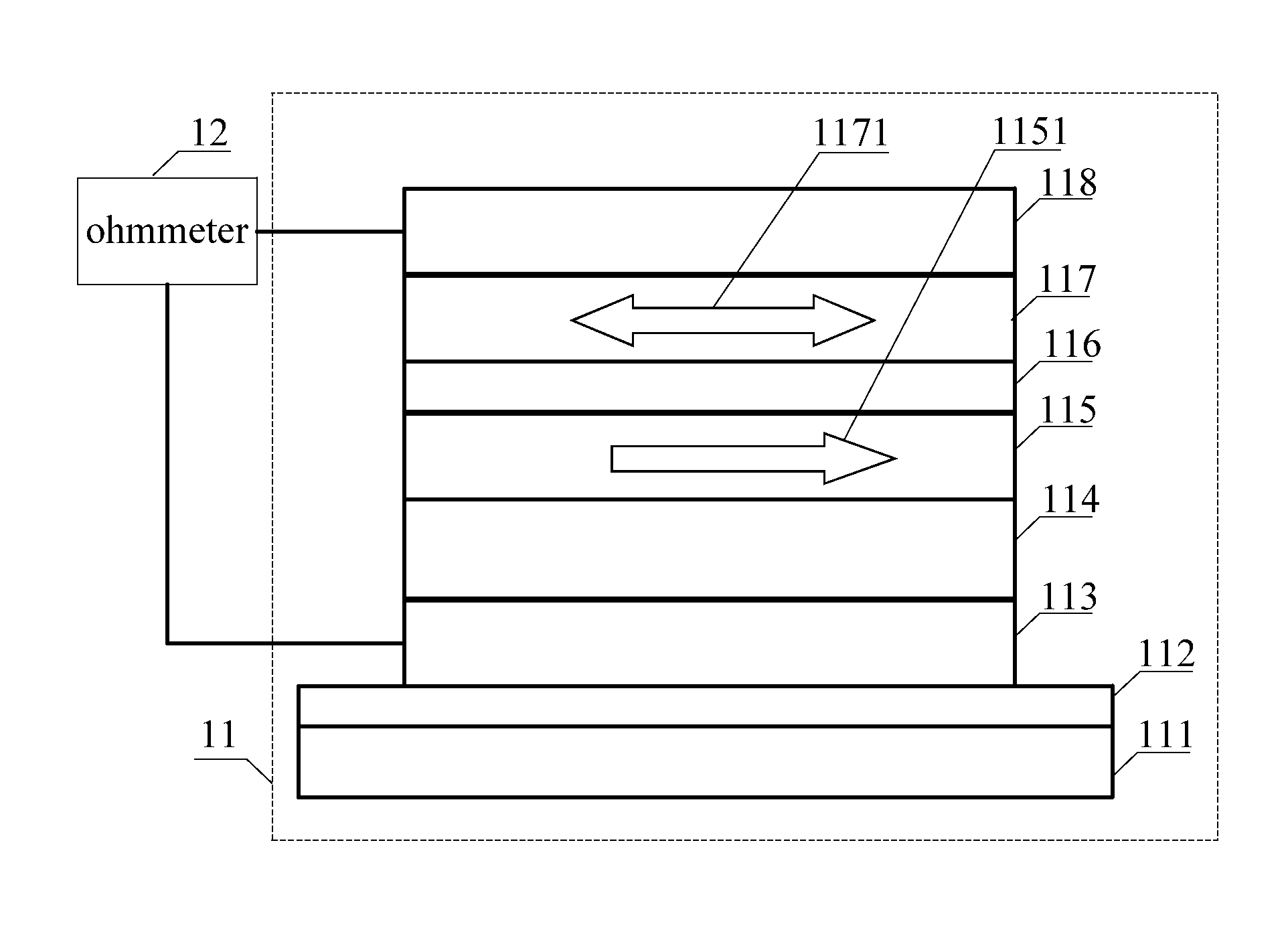
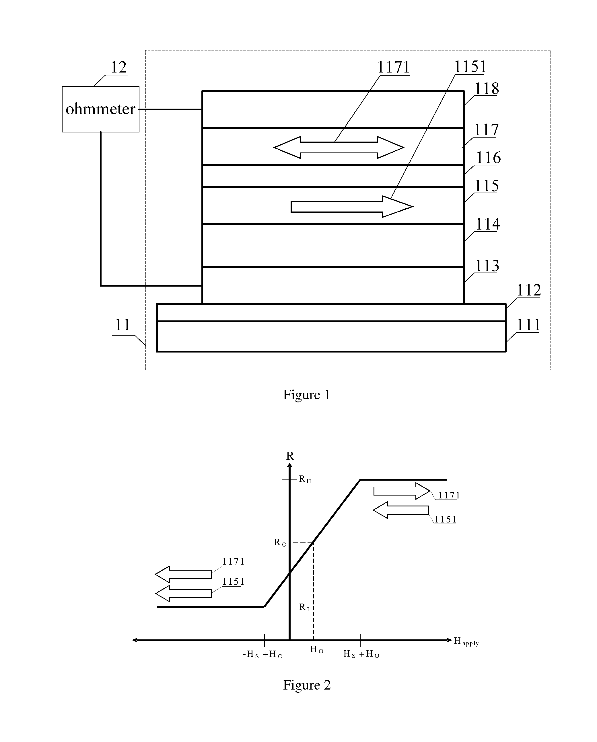
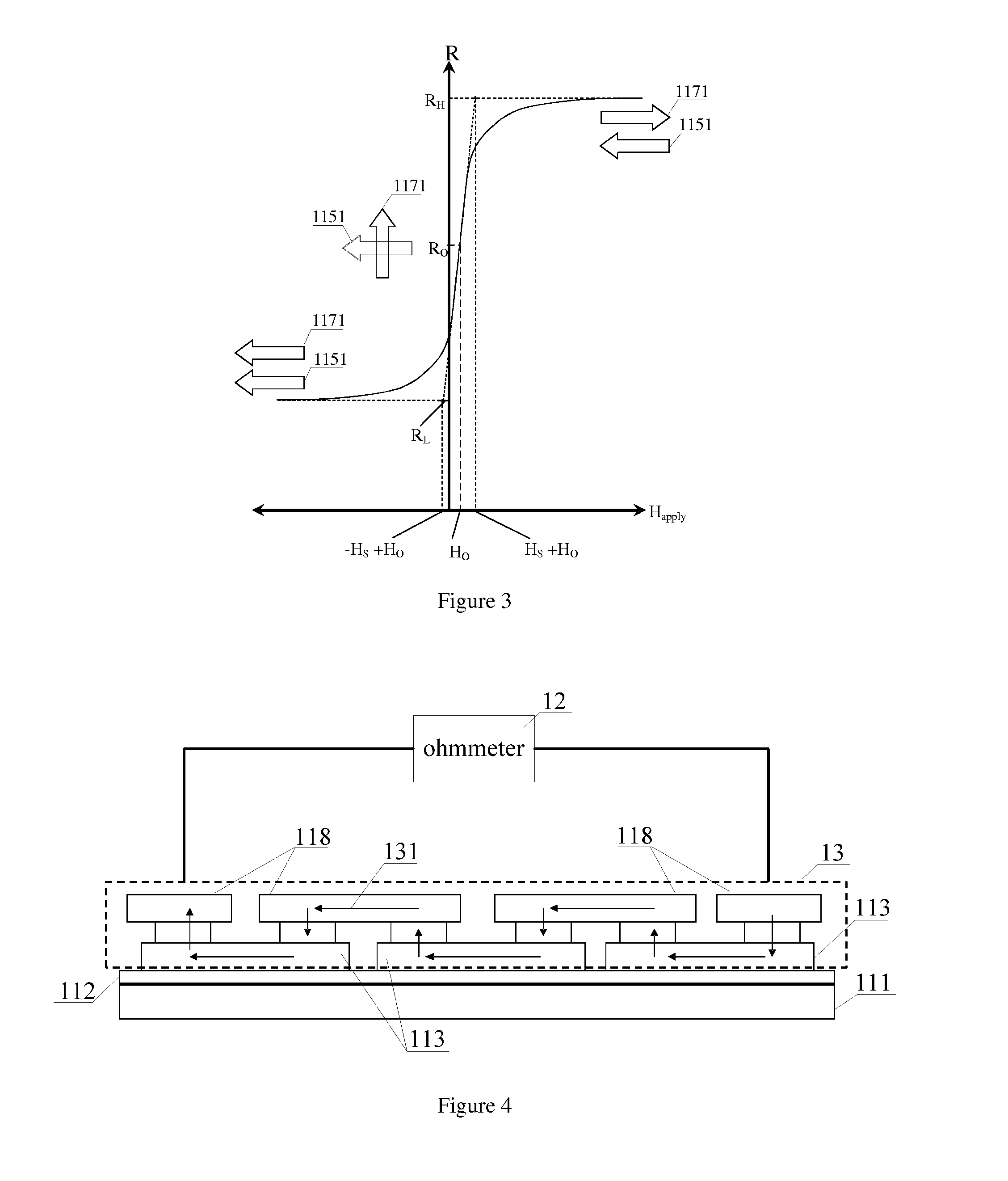
[0063]FIG. 1 shows a schematic diagram of a first embodiment of an MTJ element 11. The first embodiment of an MTJ element 11 is a multilayer film structure, shown in FIG. 1, which comprises sequentially deposited on the substrate 111, an insulating layer 112, a bottom electrode layer 113, a pinning layer 114, a pinned layer 115, a tunnel barrier layer 116, a ferromagnetic free layer 117, and a top electrode layer 118. Pinned magnetic layer 115 and ferromagnetic free layer 117 are comprised of ferromagnetic metals and alloys including Fe, Co, Ni, FeCo, FeNi, FeCoB, or FeCoNi. The pinned layer 115 may be a trilayer ferromagnetic layer, in which two ferromagnetic layer are separated by a Ru layer, for example, a FeCo / Ru / FeCo trilayer. Pinning layer 114 and pinned layer 115 are exchange coupled so that the direction of the magnetic moment 11...


PUM


Abstract

The present invention discloses a magnetoresistive gear tooth sensor, which includes a magnetoresistive sensor chip and a permanent magnet. The magnetic sensor chip is comprised of at least one magnetoresistive sensor bridge, and each arm of the sensor bridge has at least one MTJ element group. The magnetoresistive gear tooth sensor has good temperature stability, high sensitivity, low power consumption, good linearity, wide linear range, and a simple structure. Additionally, the magnetoresistive gear tooth sensor has a concave soft ferromagnetic flux concentrator, which can be used to reduce the component of the magnetic field generated by the permanent magnet along the sensing direction of the MTJ sensor elements, enabling a wide linear range. Because it is arranged as a gradiometer, the magnetoresistive gear tooth sensor bridge is not affected by stray magnetic field; it is only affected by the gradient magnetic field generated by gear teeth in response to the permanent magnet bias. The magnetoresistive gear tooth sensor of the present invention is able to detect the position of a specific tooth or a missing tooth of a gear. This magnetoresistive gear tooth sensor is also capable of determining the speed and direction of motion of a gear.

Description

CROSS-REFERENCE TO A RELATED APPLICATION[0001]This application is a 35 U.S.C. §371 national phase application of PCT / CN2013 / 076707, filed on Jun. 4, 2013, which claims a priority to a Chinese Patent Application No. CN 201210180465.0, filed on Jun. 4, 2012, incorporated herein by reference in its entirety.TECHNICAL FIELD[0002]The present invention relates to magnetic position and speed detection sensors, and particularly relates to the use of MTJ elements configured as a magnetoresistive gear tooth sensor.BACKGROUND[0003]Gear tooth sensors are mainly used in automatic control systems to measure the speed and direction of rotation of a gear. Presently, the most commonly used gear tooth sensors utilize optical or magnetic sensing. In rotating mechanical systems harsh conditions such as vibration, shock, oil, and etc. are present which are not well tolerated by optical sensing, and do not affect magnetic sensors, so magnetic sensors have advantages over optical sensors in these systems....

Claims


Application Information

Patent Timeline
IPC IPC(8): G01P3/488G01D5/14G01P13/04
CPCG01P3/488G01D5/142G01P13/045G01P3/54G01R33/093G01R33/098
Inventor BAI, JIANMINDEAK, JAMES GEZALV, HUASHEN, WEIFENG
Owner MULTIDIMENSION TECH CO LTD
Learn More