High-efficiency excitation generator automatic voltage regulator

An automatic voltage and generator technology, which is applied in the direction of controlling the generator through the change of the magnetic field, can solve the problems of troublesome production in the workshop, occupying the box combination group, and large volume, and achieves good temperature difference stability, strong anti-interference ability, and heat dissipation good performance

Inactive Publication Date: 2014-03-26
KUNGFU SCI TECH CO LTD
View PDF6 Cites 2 Cited by
  • Summary
  • Abstract
  • Description
  • Claims
  • Application Information

AI Technical Summary

Problems solved by technology

[0003] 1) The volume is large, and it is equipped with a ceramic tube variable resistor and an excitation rectifier, which occupies a large space in the box combination group, and the external wiring is complicated, which brings certain difficulties to the judgment of the cause of the fault;
[0004] 2) The waveform of the harmonic voltage has high requirements. When making a new product, it has to go through many tests and modify the harmonic to match the regulator, which brings unnecessary trouble to the workshop;
[0005] 3) When the phase of the detection voltage and the phase of the harmonic voltage cannot reach the optimal state, the silicon controlled rectifier will be turned on but delayed when it should be turned on, resulting in a decrease in the utilization rate of the excitation energy;
[0006] 4) After the harmonic voltage passes through the half-wave rectification circuit, it supplies the excitation current to the exciter. Compared with the full-wave rectification, it will reduce the efficiency and waste the harmonic copper wire;
[0008] 6) The circuit board and components of the regulator are not encapsulated with glue, which is easy to get damp, which will increase the failure rate of the regulator;
[0009] 7) It can only be used on harmonic excitation generators, and cannot be used on fundamental wave excitation and permanent magnet excitation generators;
[0010] 8) No automatic parallel function

Method used


Image

  • High-efficiency excitation generator automatic voltage regulator
  • High-efficiency excitation generator automatic voltage regulator
  • High-efficiency excitation generator automatic voltage regulator

Examples


Embodiment Construction

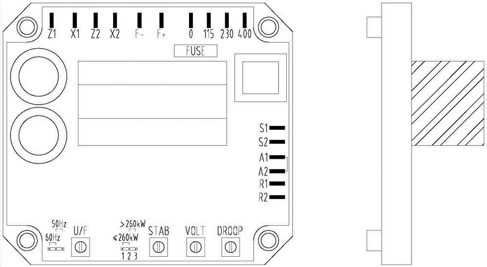
[0028] Such as figure 1 As shown, the present invention realizes the automatic adjustment of the output voltage of the generator by controlling the excitation current of the AC exciter of the generator, and is a part of the excitation system of the AC brushless generator; the product shell adopts a plastic bottom shell and is fully resin potted , the metal connector has been treated with moisture-proof and salt-spray protection, and can be used in an environment with a temperature of -40°C ~ +80°C and a humidity of 95% without frost. The external shock absorber is fixed in the combination group of the generator box; the voltage The detection circuit and excitation current regulation circuit adopt advanced design concepts and low power consumption synchronous PWM pulse width modulation technology; the product has voltage setting, stability adjustment, F / V frequency / voltage characteristic setting, F / V low frequency protection, Parallel current compensation and other functions, a...


PUM


Abstract

The invention discloses a high-efficiency excitation generator automatic voltage regulator, comprising a shell and an internal circuit, wherein the shell adopts plastic bottom case and completely encapsulated by resin, and metal connector are subjected to moistureproof and anti-salt fog treatment, so that high-efficiency excitation generator automatic voltage regulator can be used in environment at the temperature of -40 to 80 DEG C and with humidity of 95% and no frost; an external damping device is fixed in the combined group of electric generator boxes; the internal circuit comprises a voltage divider, a voltage divider, a direct current mixer, a comparison amplifying circuit, a stable feedback circuit, an electric generator slope, a horizontal detector, an excitation regulation circuit, a low-frequency detecting DIP, reference voltage, a synchronous circuit, a power supply, a low pass filter, a rectification suppression circuit and a power control device. The high-efficiency excitation generator automatic voltage regulator has the advantages that: 1, the stead-state voltage regulation factor and the temperature difference stability are good; 2, the stability is good, and thus being capable of adapting to sudden increase or reduce of load; 3, the antijamming capability is strong, and the heat dispersion is good; 4, a high-efficiency semiconductor is used in the circuit so that the lower excitation voltage (more than 5V) is ensured to be obtained by excitation.

Description

technical field [0001] The invention relates to an automatic voltage regulator, in particular to an automatic voltage regulator for high-efficiency excitation generators. Background technique [0002] With the wide application of power generation equipment, power loads put forward higher and higher requirements for power generation equipment. The electrical performance index of power generation equipment depends on the performance of the generator, which in turn depends on the performance of the generator voltage regulator. Current existing voltage regulators have the following disadvantages: [0003] 1) The volume is large, and it is equipped with a ceramic tube variable resistor and an excitation rectifier, which occupies a large space in the box combination group, and the external wiring is complicated, which brings certain difficulties to the judgment of the cause of the fault; [0004] 2) The waveform of the harmonic voltage has high requirements. When making a new p...

Claims


Application Information

Patent Timeline
IPC IPC(8): H02P9/30
Inventor 刘佳俊
Owner KUNGFU SCI TECH CO LTD
Why Eureka
Try Eureka