
Vehicle seat suspension mat

a technology for suspension mats and vehicles, applied in the field of vehicle seats, can solve the problems of high development cost, unattractive solution, and severe constraints on the implementation of technical equipment in vehicles

Inactive Publication Date: 2015-05-21
IEE INT ELECTRONICS & ENG SA
View PDF33 Cites 17 Cited by
  • Summary
  • Abstract
  • Description
  • Claims
  • Application Information

AI Technical Summary

Benefits of technology

The present invention provides a vehicle seat suspension mat that can adapt to different reference points of the seat without needing to modify the pressure sensor. The suspension mat includes one or more suspension springs for supporting the seat cushion and an occupancy sensor module supported by at least one of the suspension springs. The occupancy sensor module includes a pair of jaws that move closer together against their resiliency in response to compressive forces acting on them. The mechanical properties of the jaws are selected to activate the switch element when the compressive forces exceed a predefined threshold. The suspension mat is little or not influenced by the design of the seat parts that can be readily perceived by the user. The first and second plates are preferably made of plastic, in particular injection-molded plastic. The occupancy sensor module may comprise one or more fixation elements for attaching it to the suspension springs. The detection circuit is connected to the switch element for detecting whether the switch element is compressed by the jaws. The suspension mat can be used in a vehicle seat with a seat frame and a seat cushion supported by the suspension mat.

Problems solved by technology

With the increasing number of available options, severe constraints arise concerning the implementation of technical equipment in the vehicle.
That induces high development costs and therefore is an unattractive solution for the automotive industry.
A problem to be solved is, therefore, to find a sensor solution, which is less influenced by seat design and thus can be used for a greater variety of car seats or even car platforms.
A drawback of the vehicle seat suspension mats of the documents DE 197 52 976 A1 and DE 20 2010 003 563 U1 resides in the fact that it is necessary to adapt the characteristics of the pressure sensor for each reference of seat.

Method used


Image

  • Vehicle seat suspension mat
  • Vehicle seat suspension mat
  • Vehicle seat suspension mat

Examples


Embodiment Construction

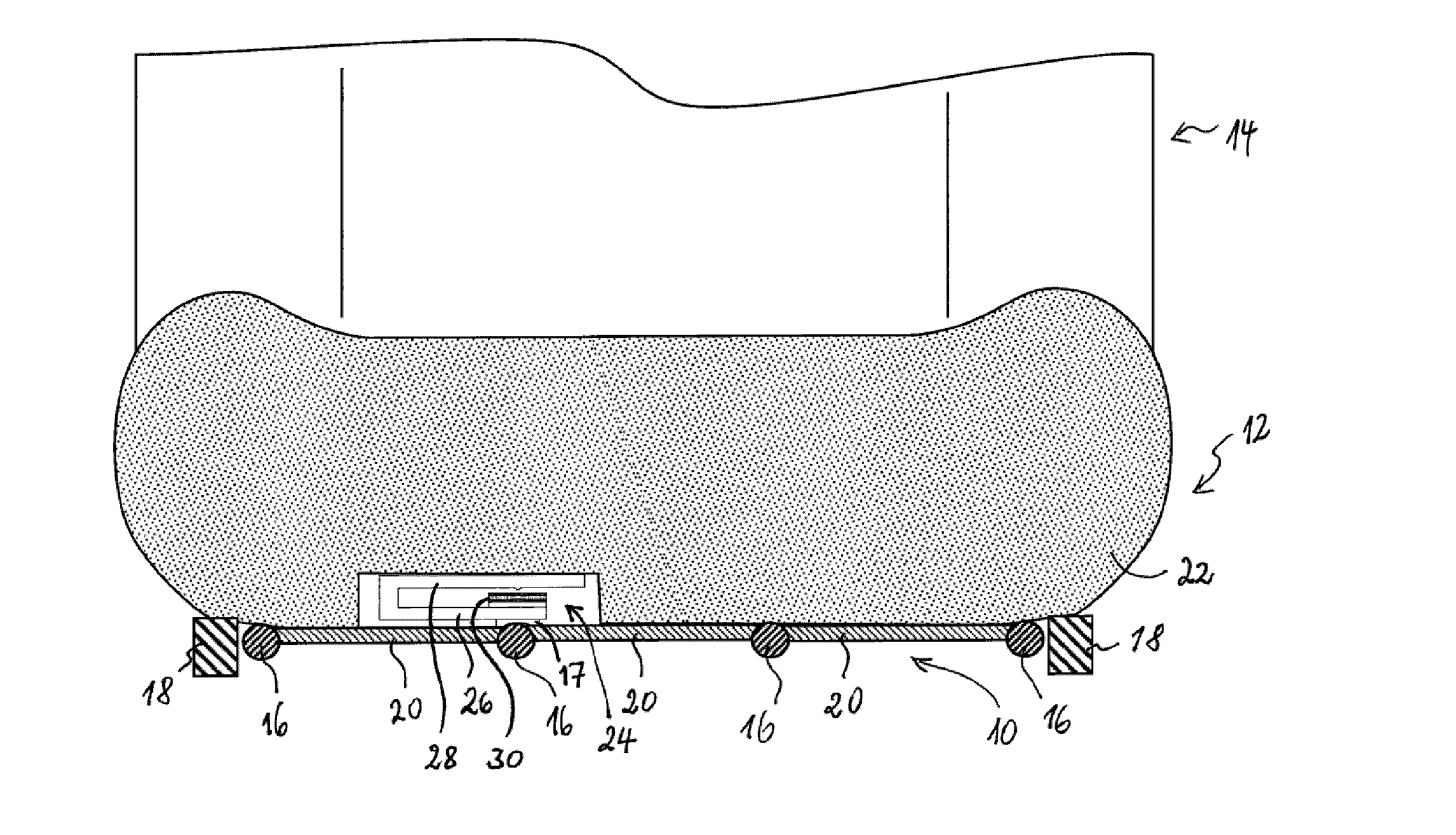
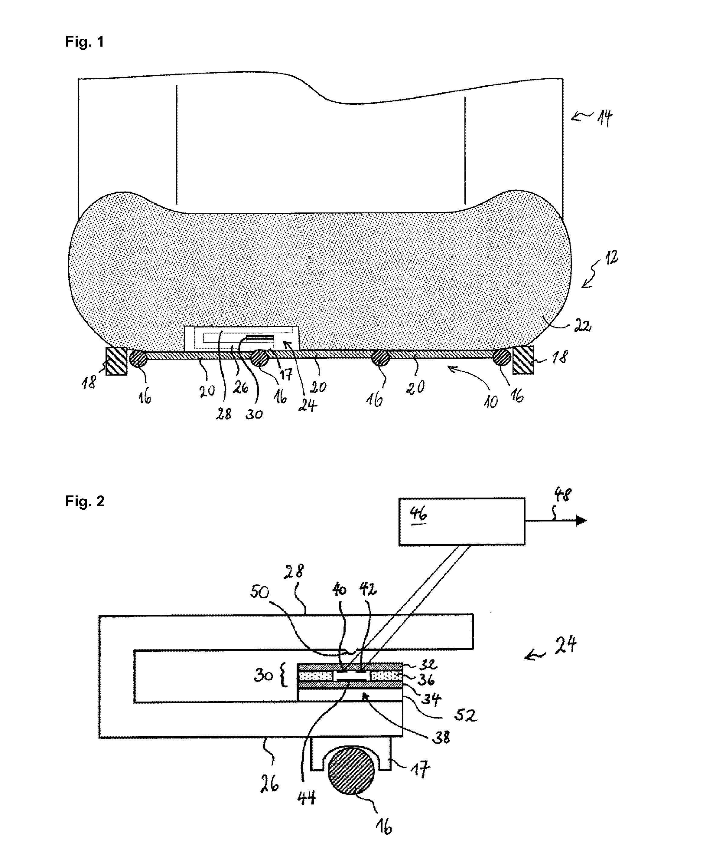
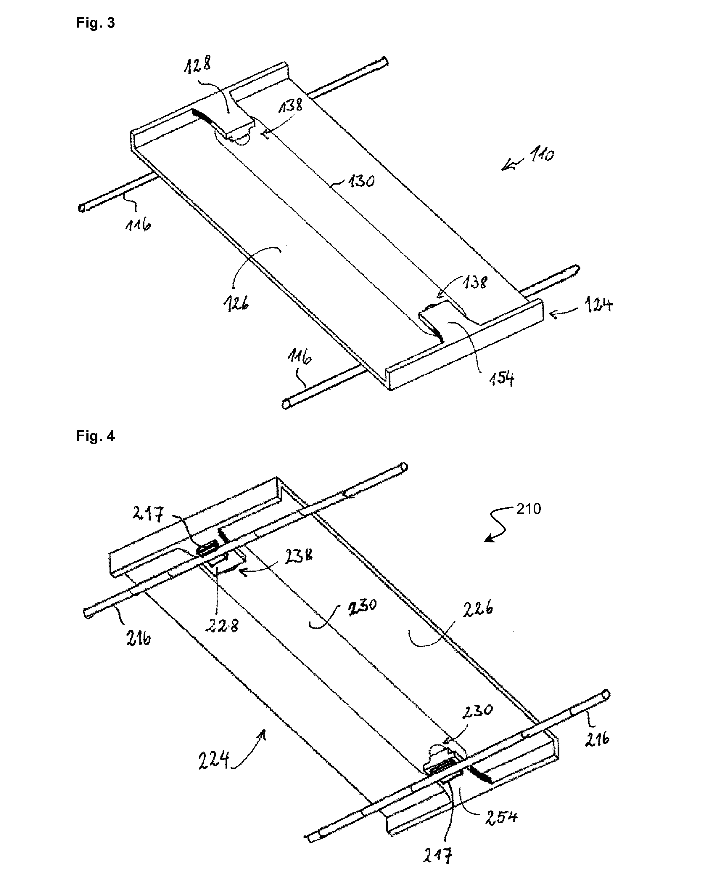
[0023]A vehicle seat suspension mat 10 according to a first preferred embodiment of the invention is shown in FIG. 1. The suspension mat 10 is part of a seating portion 12 of a vehicle seat 14. The suspension mat comprises a plurality of suspension springs 16 (e.g. made of steel wire) taut between fixation sites (not shown) of the structural frame 18 of the vehicle seat 14. The suspension springs 16 are flexibly linked to each other by plastic cross-ties 20. The suspension mat 10 supports the seat cushion 22 of the vehicle seat 14. The suspension mat 10 further includes a seat occupancy detector 24 that is responsive to the weight of a seat occupant.

[0024]The seat occupancy sensor module 24 is clipped on a suspension spring 16 by a fixation element or clip 17. As best illustrated in FIG. 2, the seat occupancy sensor module 24 comprises a first 26 and a second plate 28 mounted in cantilevered manner on the first plate 26. The first and second plates 26, 28 are made of injection-molde...


PUM

PropertyMeasurementUnit
compressive forcesaaaaaaaaaa
pressure-aaaaaaaaaa
pressureaaaaaaaaaa

Abstract

A vehicle seat suspension mat (10) comprises one or more suspension springs (16) for supporting a seat cushion (22) and an occupancy sensor module (24) supported by at least one suspension spring. The module includes a first plate (26) having a switch element (38) arranged thereon and a second plate (28) mounted in a cantilevered manner to the first plate, in such a way that the first and second plates form together a pair of jaws, which the switch element is arranged between. The first and second plates are configured so as to move closer together against their resiliency in response to compressive forces acting on the first and second plates.

Description

TECHNICAL FIELD[0001]The present invention generally relates to the field of vehicle seats. In particular, the invention relates to a vehicle seat suspension mat.BACKGROUND ART[0002]Seat occupancy sensors are nowadays widely used in automotive vehicles to provide a seat occupancy signal for various appliances, such as, e.g. a seat belt reminder, an auxiliary restraint system (airbag), etc. The possibility of customization and personalization of the vehicle by the customer is a key selling factor of modern cars. This leads to many different variants of car interiors being offered for one car model. With the increasing number of available options, severe constraints arise concerning the implementation of technical equipment in the vehicle. With seat occupancy sensors arranged between the foam body of the seat cushion and the seat cover, every seat design (leather, cloth, sport, comfort, . . . ) requires specific development effort for the occupant detection system. That induces high d...

Claims


Application Information

Patent Timeline
Patent Type & Authority Applications(United States)
IPC IPC(8): B60N2/00G01L1/22B60N2/68B60N2/54
CPCB60N2/002B60N2/68G01L1/22B60N2/54B60N2/7094B60R21/015H01H13/705H01H13/702B60N2210/46B60N2/0032B60R21/01524
Inventor GOEDERT, GUENTER
Owner IEE INT ELECTRONICS & ENG SA
Learn More