
Aircraft brake assembly

a technology for aircraft and brakes, applied in aircraft braking arrangements, aircraft components, landing gears, etc., can solve the problems of aircraft slowdown, substantial stress and strain on landing gear components, added weight and complexity, etc., to prevent undue stress and strain, reduce vibration and oscillation in the second sub-assembly, and prevent undesired movement

Active Publication Date: 2015-05-21
MESSIER DOWTY
View PDF3 Cites 10 Cited by
  • Summary
  • Abstract
  • Description
  • Claims
  • Application Information

AI Technical Summary

Benefits of technology

The technical effect of this patent is that it describes how to prevent unwanted movements of an aircraft's landings gear while it is on the ground and in the air. This prevents damage to components and ensures safe operation. Dampers and stops are used to achieve these goals. Additionally, by biasing the landings gear at takeoff, the main wheels can touch down first without damaging any parts.

Problems solved by technology

The technical problem addressed in this patent relates to reducing excessive stress and strain placed on aircraft landing gear components caused by applying brakes during landings, while still ensuring effective braking performance.

Method used


Image

  • Aircraft brake assembly
  • Aircraft brake assembly
  • Aircraft brake assembly

Examples


Embodiment Construction

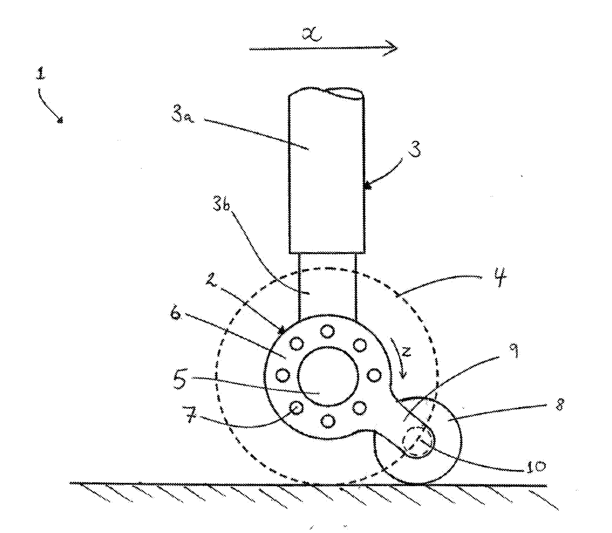
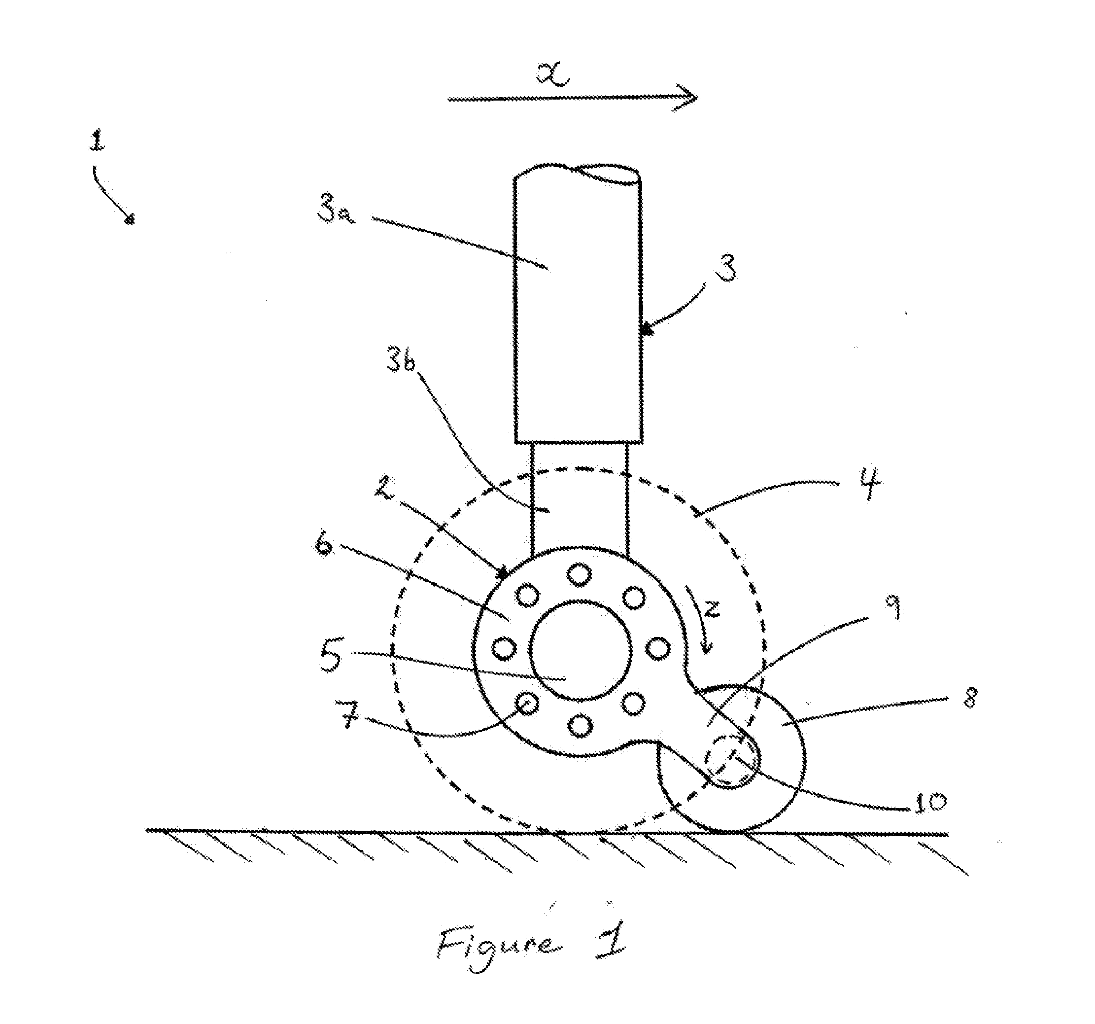
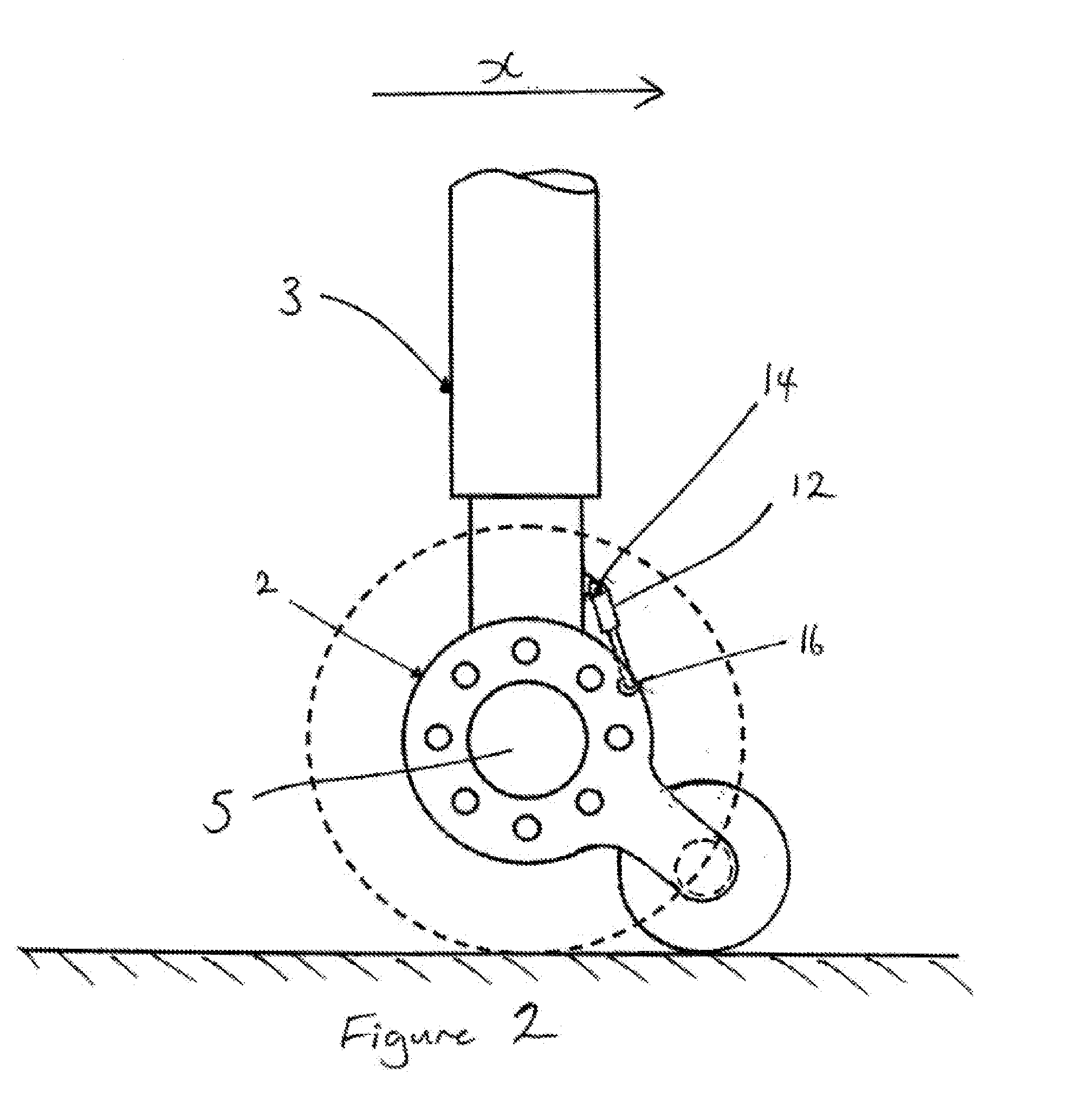
[0020]FIG. 1 shows an aircraft landing gear 1 including a brake assembly 2 according to an embodiment of the present invention, the aircraft landing gear 1 being on the ground. The aircraft landing gear 1 comprises a telescopic support leg 3 including upper and lower portions 3a, 3b. Embodiments described herein comprises a telescopic support leg. However, the skilled person will appreciate that the present invention is equally applicable to aircraft landing gear comprising fixed landing gear legs. In the embodiment illustrated, the landing gear is a main landing gear having a single pair of main wheels 4 located at either end of an axle 5, which may form part of the lower portion 3b of the telescopic support leg 3. The skilled person will appreciate that this design could be implemented on a main landing gear with a bogie beam having two or more pairs of tyres, with the mechanism described herein incorporated into one or more of the wheels and associated brakes. The aircraft landin...


PUM


Abstract

An aircraft brake assembly comprising a support leg, a main wheel rotatably mounted on the support leg, a brake comprising a first sub-assembly fixed to the main wheel and a second sub-assembly moveably mounted on the support leg and a ground reaction wheel coupled to the second sub-assembly, wherein on application of the brake, the first sub-assembly engages with the second sub-assembly to exert a braking force on the second sub-assembly; and wherein the ground reaction wheel is arranged to transfer the braking force from the second sub-assembly to the ground.

Description


Claims


Application Information

Patent Timeline
Owner MESSIER DOWTY
Learn More