
Apparatus for applying film material to elongate members

a film material and apparatus technology, applied in the application of film over a substrate, can solve the problems of affecting the risk of damage to the edge of the base flange, and the time-consuming and labor-intensive multi-stage process that is currently time-consuming and laborious, so as to reduce the time of process flow and recurring costs, improve the uniformity and fit of the film material, and improve the effect of material utilization

Active Publication Date: 2015-05-21
THE BOEING CO
View PDF1 Cites 5 Cited by
  • Summary
  • Abstract
  • Description
  • Claims
  • Application Information

AI Technical Summary

Benefits of technology

The patent describes a machine and process for applying a film material to long structures such as composite stringers, spars, beams, and doublers. This machine, called a film applicator, can reduce process time, recurring costs, and improve material utilization. It also helps achieve uniformity in the film material and reduces potential damage to the structure's edges. Most importantly, the film applicator is simple, reliable, and easy-to-use, requiring no on-board motors or automated controls. It can be easily set up and operated manually by production workers.

Problems solved by technology

Preparing long composite structural members such as aircraft stringers for an adhesive bonding operation is a multi-stage process that is currently time consuming and labor intensive.
This hand trimming technique may be tedious, time-consuming and presents the risk of damage to edges of the base flange, particularly where the flange is beveled.
During hand trimming, foreign object debris may be produced which, if adhered to the stringer, may affect the desirability of the bond.
The film material applicator and related application method may reduce process flow time, as well as recurring costs including labor and materials.

Method used


Image

  • Apparatus for applying film material to elongate members
  • Apparatus for applying film material to elongate members
  • Apparatus for applying film material to elongate members

Examples


Embodiment Construction

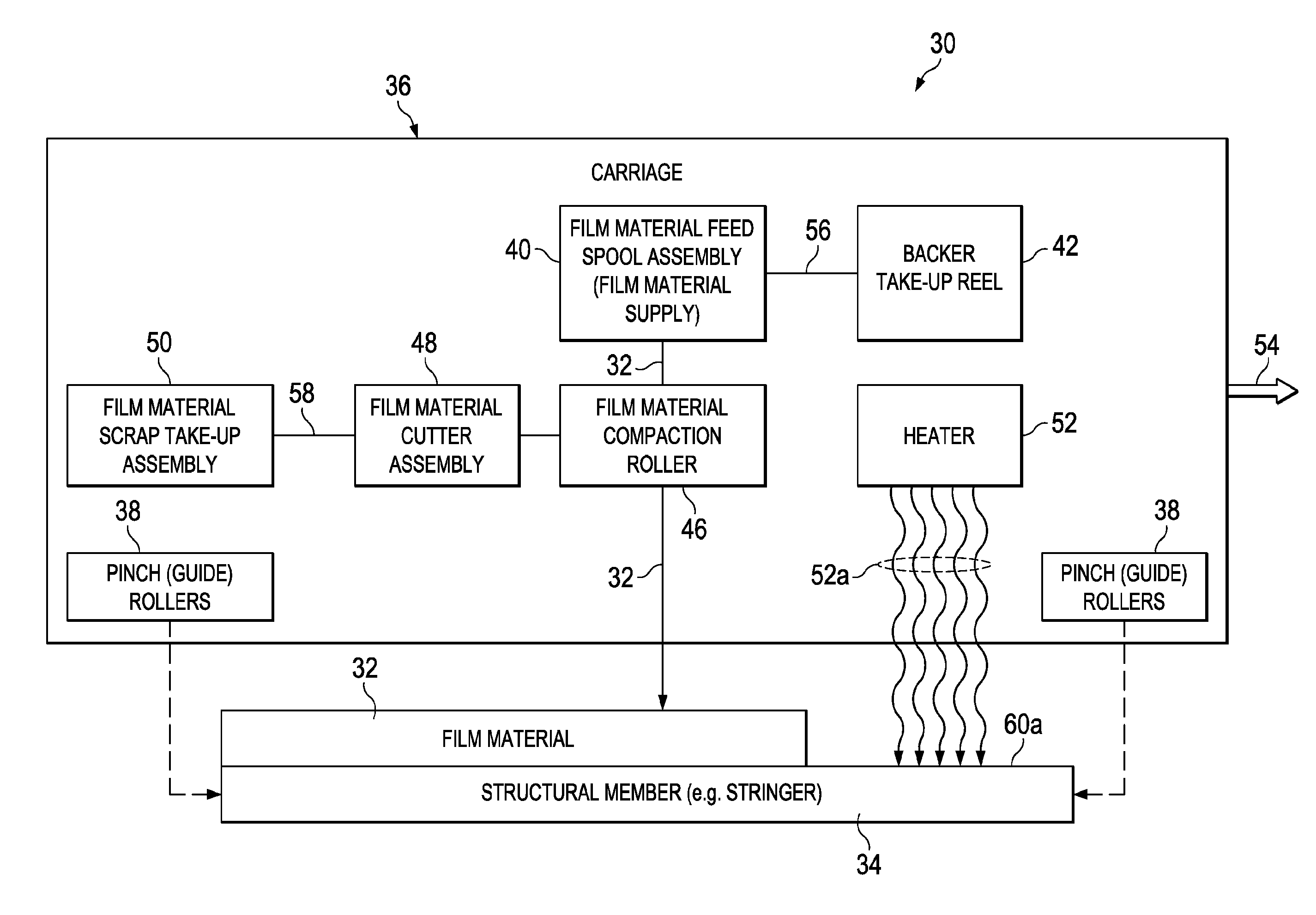
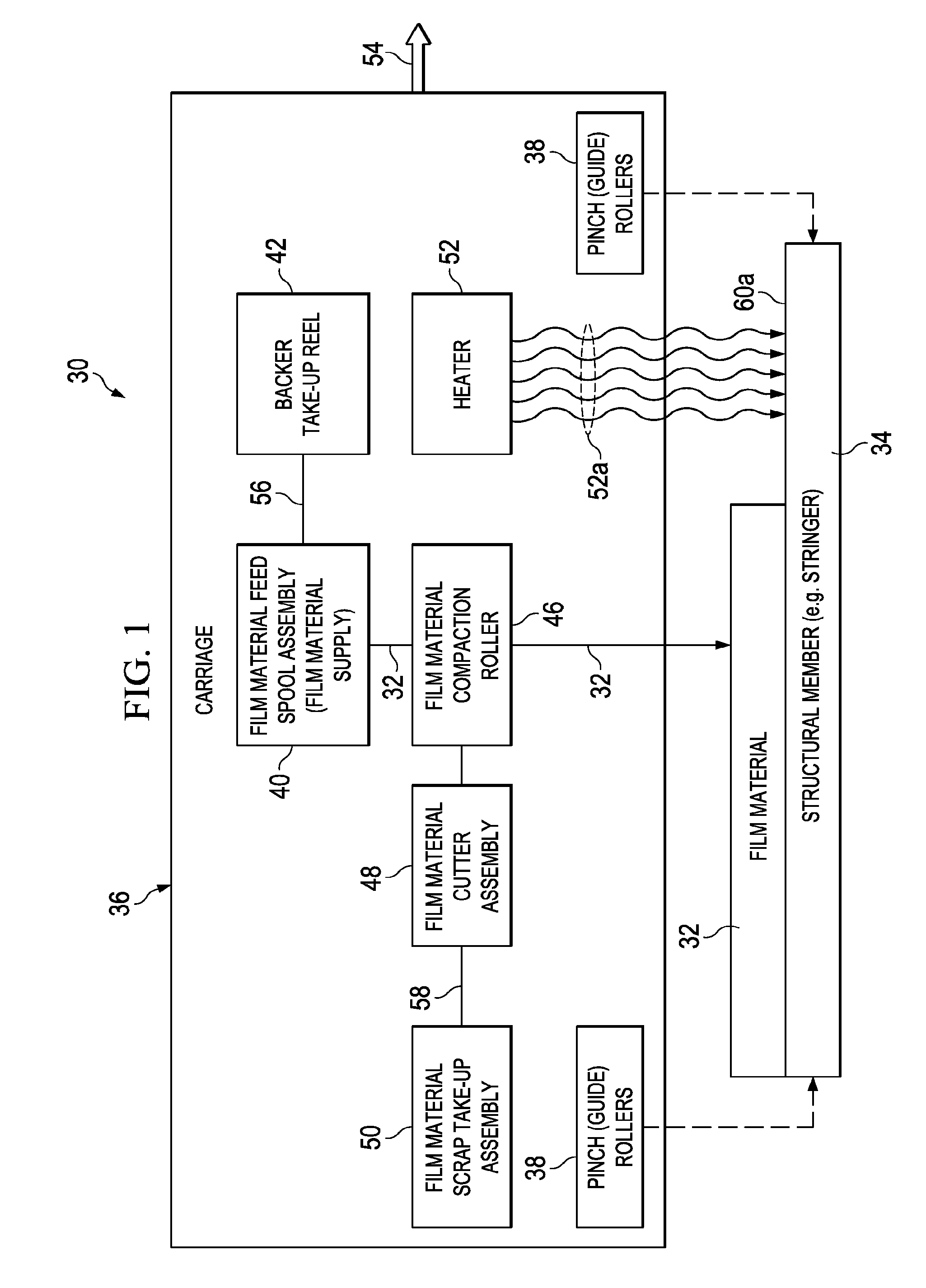
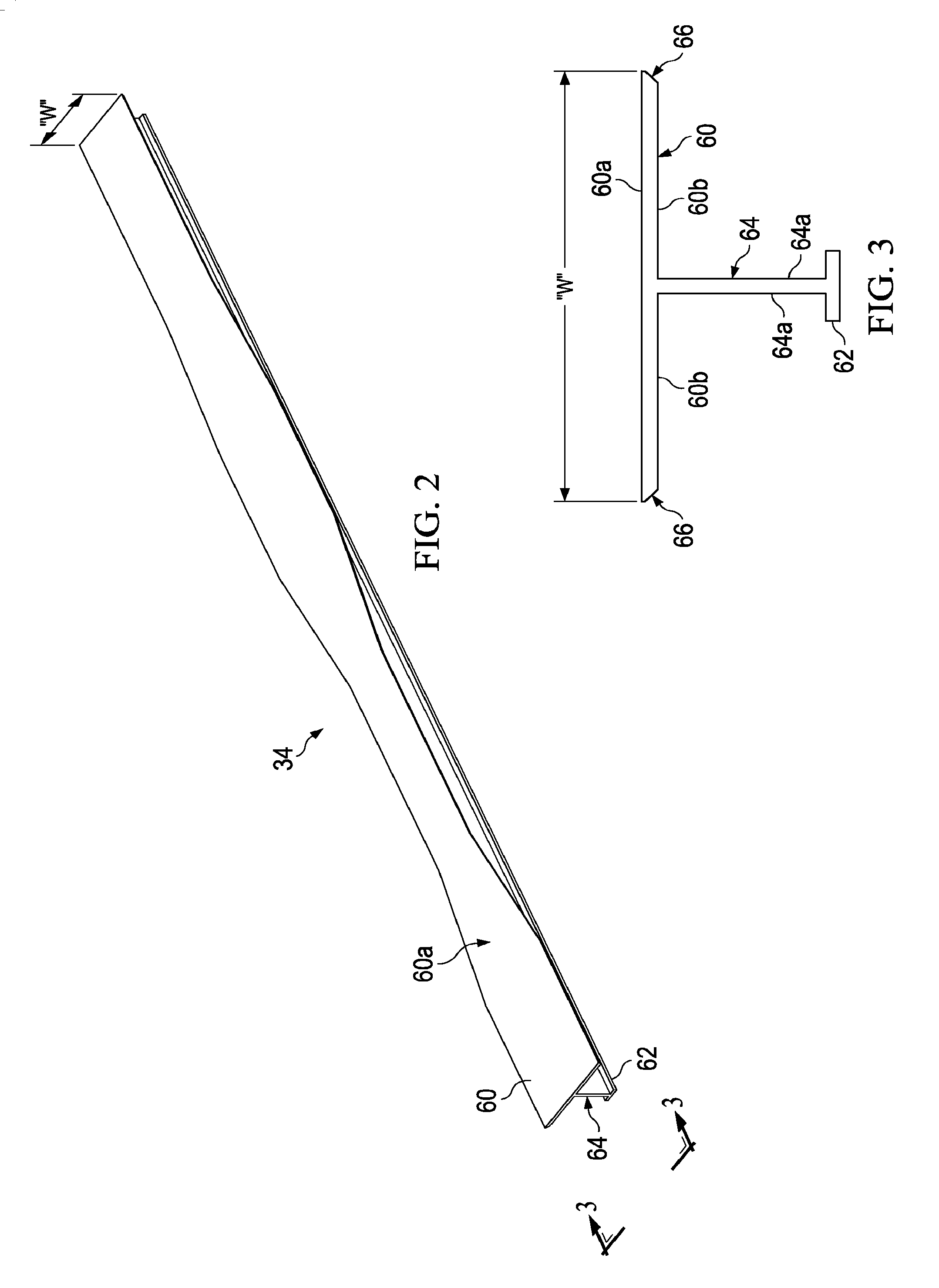
[0039]Referring first to FIG. 1, the disclosed embodiments relate to an apparatus 30 for dispensing, placing, compacting and trimming film material 32 on the surface 60a of elongate structural member 34. For simplicity of description the apparatus 30 will be hereinafter referred to as a film applicator 30, and the film material 32 may be referred to as film 32, material 32 or film material 32. In the illustrated example discussed below in more detail, the structural member 34 is a composite stringer, however it is to be understood that the film applicator 30 may be employed to apply film material 32 to the surface of any long, relatively narrow members such as, without limitation, spars, beams, doublers, etc. The film material 32 may comprise any relatively thin, flexible material that is required to be applied to the elongate structural member 34, such as without limitation, an adhesive.

[0040]The film applicator 30 comprises several functional components discussed below that are mo...


PUM

PropertyMeasurementUnit
lengthaaaaaaaaaa
thicknessaaaaaaaaaa
lengthaaaaaaaaaa

Abstract

An apparatus including a carriage adapted to be mounted on and movable along the elongate composite stringer, and a compaction roller mounted on the carriage for compacting film material against the flange surface as the carriage moves along the stringer. The apparatus also includes a film feed roll assembly on the carriage adapted to hold a quantity of film material and to dispense the film material to the compaction roller. The apparatus also includes a take-up reel on the carriage adapted for taking up a backing on the film material as the film material is being dispensed to the compaction roller, a heater on the carriage for heating the flange surface as the carriage moves along the composite stringer, and a film trimmer for trimming edges of the film material to match a contour of the composite stringer after the film material has been compacted against the flange surface.

Description

[0001]This application is a divisional application of U.S. patent application Ser. No. 13 / 690,809, filed Nov. 30, 2012.BACKGROUND INFORMATION[0002]1. Field[0003]The present disclosure generally relates to the application of film over a substrate, and deals more particularly with a method and apparatus for applying and trimming a film material along a surface of an elongate structural member, such as a composite stringer.[0004]2. Background[0005]Composite and other structures may be bonded together using a structural film adhesive material which may include a carrier such as a scrim for controlling bondline thickness. For example, in the aircraft industry, a composite stringer may be joined to another composite part such as a skin by co-bonding, or in a secondary bonding operation using a structural film adhesive material that is applied over the surface of a flange on the stringer. The stringer flange with the applied film adhesive is placed against the skin and the film adhesive is...

Claims


Application Information

Patent Timeline
Patent Type & Authority Applications(United States)
IPC IPC(8): B32B37/20B32B38/00B32B38/18B32B37/10
CPCB32B37/20B32B37/10B32B2250/02B32B38/18B32B38/0004B29C63/024B29L2031/003B29C2793/00B29C70/38B29D99/0003Y10T156/108Y10T156/1317Y10T156/1348Y10T156/1795B29C2793/0036B32B37/0053B32B2038/045B29D99/001
Inventor SCHAAF, AMERICA O.MILLER, RICHARD A.ANDERSON, DONALD A.
Owner THE BOEING CO
Learn More