
Engine fuel delivery system

a fuel delivery system and engine technology, applied in the field of engine fuel delivery systems, can solve the problems of short supply of alternative fuels, affecting the supply of fuels, and suffering a significant price disadvantage in comparison with standard kerosen

Active Publication Date: 2015-05-14
ROLLS ROYCE PLC
View PDF5 Cites 9 Cited by
  • Summary
  • Abstract
  • Description
  • Claims
  • Application Information

AI Technical Summary

Benefits of technology

The invention is a system for reducing emissions from aircraft engines during the landing and take-off cycle, which can negatively impact air quality. The system includes a controller that uses machine-readable instructions to control the regulator. This reduces particulate matter emissions from the engine and also reduces the kerosene content of fuel burned by the engine. The controller can adjust the engine operating condition sensor, such as the throttle or thrust setting, to achieve this reduction. The technical effect is the reduction of emissions from aircraft engines during the LTO cycle, leading to improved air quality and reduced engine impact on the local environment.

Problems solved by technology

However U.S. Pat. No. 8,311,686B does not provide any executive action or decisions for ways to actually reduce emissions but rather requires human interpretation of the output information in order to decide what action may be most appropriate.
Currently, alternative fuels (particularly biofuels) suffer a very significant price disadvantage in comparison with standard kerosene, and are in short supply.
There are also technical limitations which prevent in many cases the complete substitution of kerosene with an alternative aircraft fuel and so, if such alternative fuels are used at all, they are typically supplied to aircraft in a predetermined blend comprising a high percentage of kerosene (representing the majority component within the blended fuel) and an alternative fuel (representing the minority component within the blended fuel).

Method used


Image

  • Engine fuel delivery system
  • Engine fuel delivery system
  • Engine fuel delivery system

Examples


Embodiment Construction

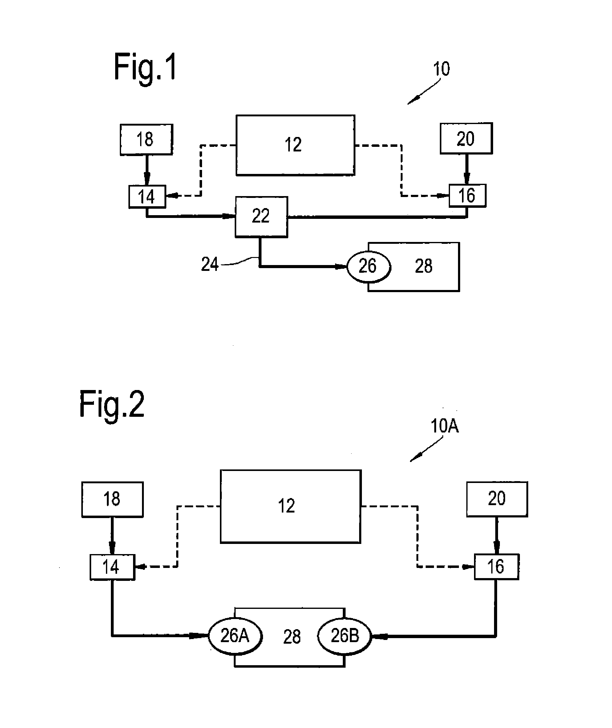
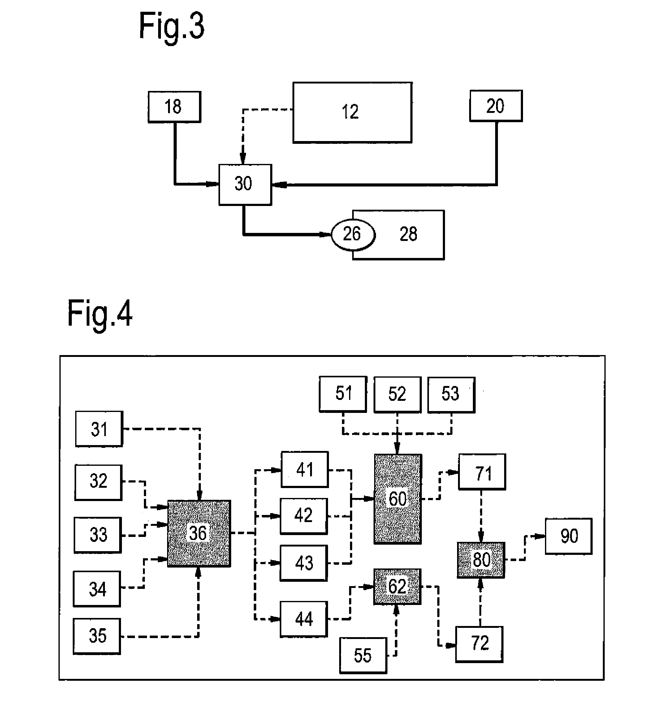
[0038]FIG. 1 shows a diagrammatic representation of a fuel system 10 installed onboard an aircraft. The arrows with solid lines indicate the fuel flow communication path, and the arrows with dashed lines indicate signal communication routes.

[0039]The fuel system 10 has a control unit 12 which is in signal communication with a first fuel composition regulator 14 and a second fuel composition regulator 16. Each fuel composition regulator 14, 16 is in fluid communication with a source 18, 20 of its respective fuel composition. The source of the first fuel composition is a first tank 18 for storage of a first fuel composition, and the source of the second fuel composition is a second tank 20 for storage of a second fuel composition. The number of fuel composition regulators and / or fuel tanks is dependent upon the number of fuel compositions with which the system is configured to operate and could, for example, include a third or fourth regulator / tank or more as necessary.

[0040]The tanks...


PUM


Abstract

This invention concerns a fuel delivery system for an aircraft engine, including a fuel delivery regulator arranged to receive fuel from a plurality of fuel sources for supply to the engine. An engine operating condition sensor reading is received by a control unit arranged to control operation of the regulator. The control unit actuates the regulator based on a received signal from the engine operating condition sensor in order to vary the volume of fuels from the plurality of fuel sources supplied to the engine during at least a portion of the landing / take-off (LTO) cycle relative to a further portion of the aircraft flight. The different fuels may include kerosene and an alternative fuel, such as a biofuel.

Description

BACKGROUND OF THE INVENTION[0001]The present invention relates to fuel delivery systems for engines and, more particularly, for aircraft engines.[0002]An important focus of improvements to aircraft engine operation concerns the reduction of greenhouse gas emissions due to fuel consumption. Whilst this is a concern for the whole life-cycle of aircraft engines, there is also a more specific consideration of local air quality (LAQ) in the vicinity of airports.[0003]U.S. Pat. No. 8,311,686B discloses a method for assessing engine emissions and / or noise at a collection of ground-based monitoring stations, and presenting the results of that assessment to pilots such that they may determine and implement appropriate actions to minimise the emissions / noise at each of the ground stations. The assessment makes use of information such as aircraft location / altitude relative to each ground station, wind-speed / direction, and engine operation parameters influencing the quantity of emissions actual...

Claims


Application Information

Patent Timeline
Patent Type & Authority Applications(United States)
IPC IPC(8): B64D37/30B64D45/00
CPCB64D45/00B64D37/30F05D2270/081F02C3/20F02C7/236F02C9/40F05D2270/07Y02T50/678Y02T50/60
Inventor SWANN, PETER
Owner ROLLS ROYCE PLC
Learn More