
Image correcting apparatus and method for imaging device

Active Publication Date: 2015-05-14
SAMSUNG ELECTRO MECHANICS CO LTD
View PDF5 Cites 22 Cited by
  • Summary
  • Abstract
  • Description
  • Claims
  • Application Information

AI Technical Summary

Benefits of technology

The invention is about an apparatus and method for improving image quality by preventing blurring caused by handshake. It uses an optical image stabilizer to correct any displacement in the image. This technology ensures that the image is clear and sharp, even in cases of handshake.

Problems solved by technology

Generally, when a user captures an image of a subject, handshaking occurs, and a digital imaging device, such as a camera, may be shaken due to handshaking.
Such shaking causes an image input through an image sensor to be shaken to result in a degradation of quality of an imaging outcome.
First, displacement of a lens shift in an OIS module is very small.
This is because an OIS module itself has a limitation in size.
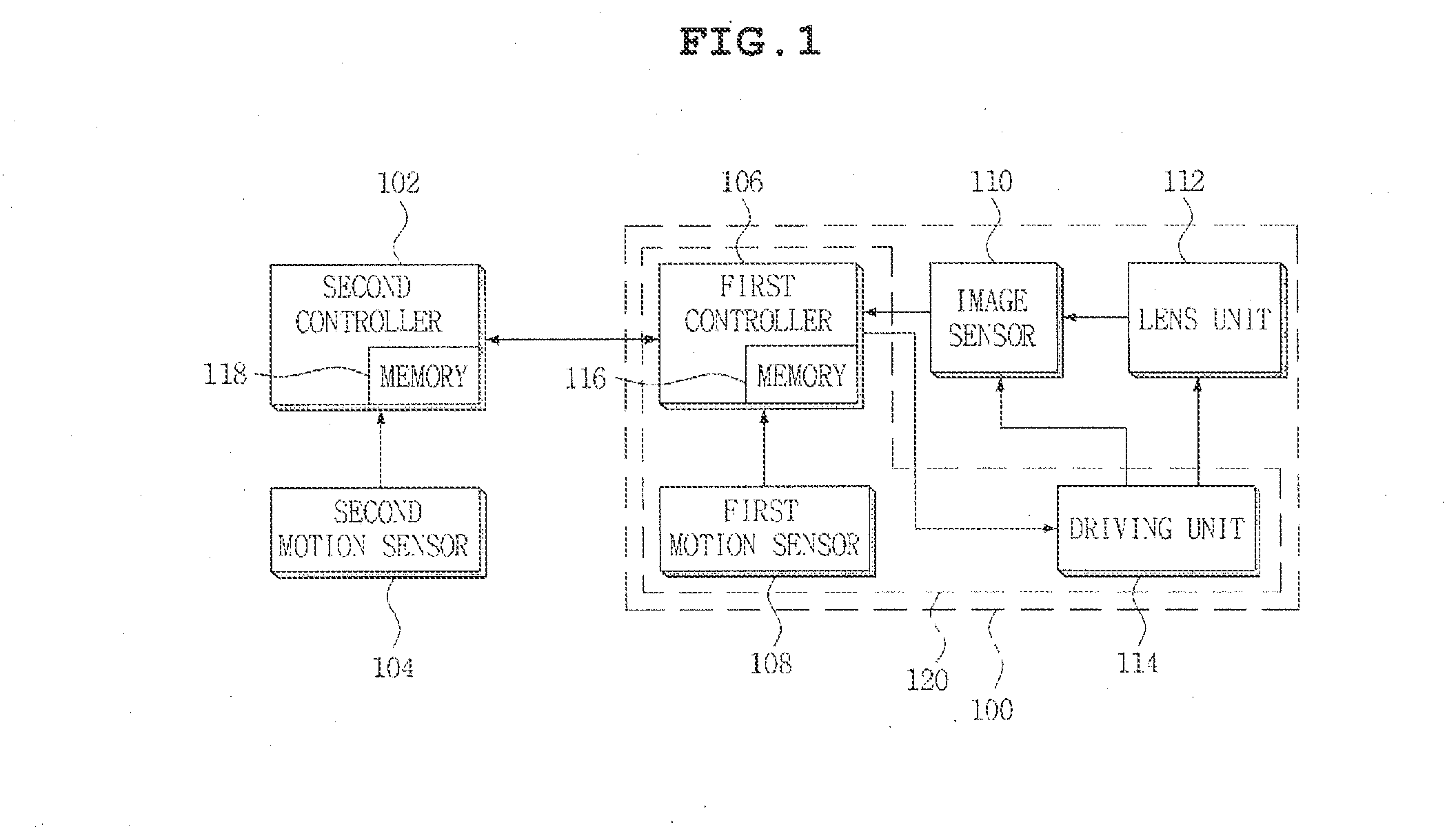
Second, an operation range of a motion sensor within an OSI module to measure handshaking is very narrow.
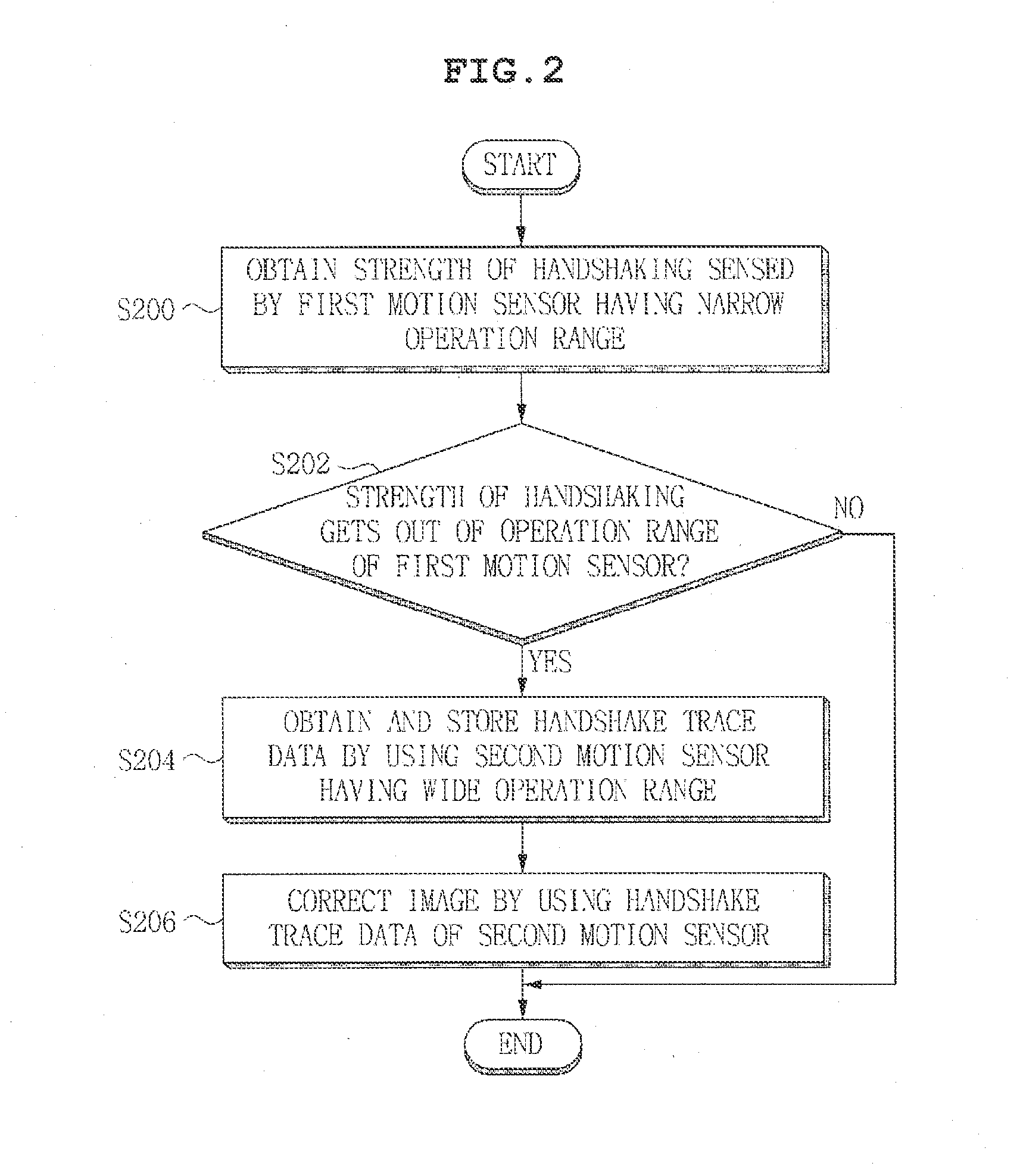
However, when an exposure duration lengthens, the shake correcting method and apparatus described in U.S. Pat. No. 8,373,761 lack the ability to prevent generation of blur in an image in a case in which displacement of handshaking is at an angle equal to or greater than a correction angle of an OIS module even for a short time during a long period of time.

Method used


Image

  • Image correcting apparatus and method for imaging device
  • Image correcting apparatus and method for imaging device
  • Image correcting apparatus and method for imaging device

Examples


Embodiment Construction

[0048]Advantages and features of the present invention and methods of accomplishing the same will be apparent by referring to embodiments described below in detail in connection with the accompanying drawings. However, the present invention is not limited to the embodiments disclosed below and may be implemented in various different forms. The embodiments are provided only for completing the disclosure of the present invention and for fully representing the scope of the present invention to those skilled in the art.

[0049]For simplicity and clarity of illustration, the drawing figures illustrate the general manner of construction, and descriptions and details of well-known features and techniques may be omitted to avoid unnecessarily obscuring the discussion of the described embodiments of the invention. Additionally, elements in the drawing figures are not necessarily drawn to scale. For example, the dimensions of some of the elements in the figures may be exaggerated relative to ot...


PUM


Abstract

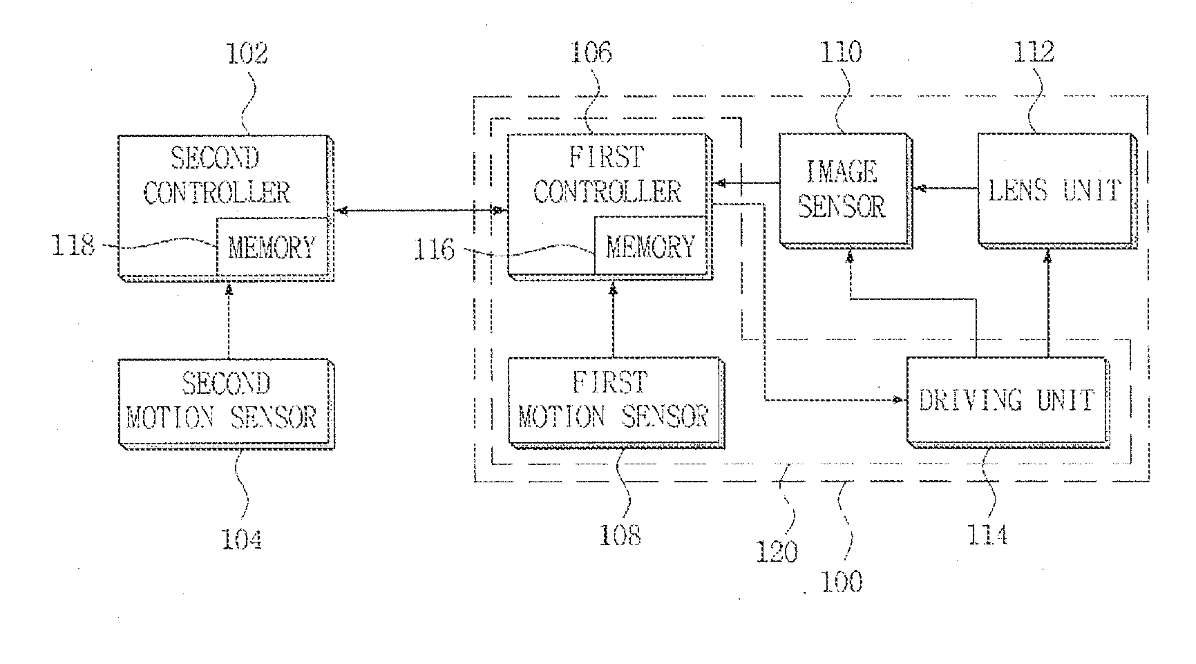
Embodiments of the invention provide an image correcting apparatus for an imaging device including a camera module having a first motion sensor. The image correct apparatus includes a second motion sensor sensing a movement, and a controller determining whether the movement gets out of an operation range of the first motion sensor, and correcting an image obtained from the camera module based on movement data sensed by the second motion sensor, when the movement gets out of the operation range of the first motion sensor. Generation of blur in an image when a displacement of handshaking is at an angle equal to or greater than a correction angle of an optical image stabilizer (OIS) module is prevented, and thus, a clear image is obtained.

Description

CROSS REFERENCE TO RELATED APPLICATION[0001]This application claims the benefit of and priority under 35 U.S.C. §119 to Korean Patent Application No. KR 10-2013-0135496, entitled “Image Correcting Apparatus and Method in Imaging Device,” filed on Nov. 8, 2013, which is hereby incorporated by reference in its entirety into this application.BACKGROUND[0002]1. Field of the Invention[0003]The present invention to an image correcting apparatus and method in an imaging device.[0004]2. Description of the Related Art[0005]Generally, when a user captures an image of a subject, handshaking occurs, and a digital imaging device, such as a camera, may be shaken due to handshaking. Such shaking causes an image input through an image sensor to be shaken to result in a degradation of quality of an imaging outcome.[0006]Recently, cameras have becoming smaller and lighter, and thus, handshaking intensifies, and as imaging is increasingly performed while on the move, solution to the problem of shake h...

Claims


Application Information

Patent Timeline
IPC IPC(8): H04N5/232
CPCH04N5/23258H04N5/23267H04N23/6812H04N23/685G06T5/00H04N23/683
Inventor HYUN, HAE SEUNGLEE, HEE BUM
Owner SAMSUNG ELECTRO MECHANICS CO LTD
Learn More