
Plenoptic camera device and shading correction method for the camera device

a camera device and shading correction technology, applied in the field of plenoptic camera devices and shading correction methods for plenoptic camera devices, can solve the problem that the shading correction method used in a general camera cannot be applied to the plenoptic camera devices

Inactive Publication Date: 2015-05-14
SAMSUNG ELECTRONICS CO LTD
View PDF4 Cites 14 Cited by
  • Summary
  • Abstract
  • Description
  • Claims
  • Application Information

AI Technical Summary

Benefits of technology

The patent text describes a camera device that can correct the issue of vignetting, which refers to a distortion where the edges of an image appear to be brighter or darker than the center. The device uses a special block that removes the vignetting effect by adjusting the gain, which is a measure of the brightness or darkness of an image. The technical effect of this invention is to improve the quality of images captured by the camera device and reduce distortion in the final output.

Problems solved by technology

When the vignetting effect is generated in the plenoptic camera device, a shading correction method that is used in a general camera cannot be applied to the plenoptic camera device.

Method used


Image

  • Plenoptic camera device and shading correction method for the camera device
  • Plenoptic camera device and shading correction method for the camera device
  • Plenoptic camera device and shading correction method for the camera device

Examples


Embodiment Construction

[0062]Example embodiments are described below in sufficient detail to enable those of ordinary skill in the art to embody and practice inventive concepts. It is important to understand that inventive concepts may be embodied in many alternate forms and should not be construed as limited to example embodiments set forth herein.

[0063]Various example embodiments will now be described more fully with reference to the accompanying drawings in which example embodiments are shown. Inventive concepts may, however, be embodied in different forms and should not be construed as limited to the embodiments set forth herein. Although a few example embodiments of inventive concepts have been shown and described, it would be appreciated by those of ordinary skill in the art that changes may be made in example embodiments without departing from the principles and spirit of inventive concepts, the scope of which is defined in the claims and their equivalents.

[0064]It will be understood that, although...


PUM


Abstract

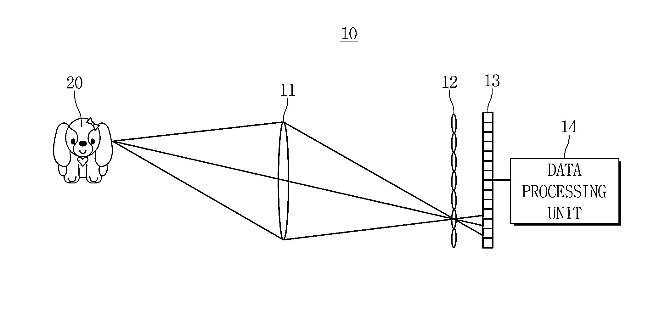
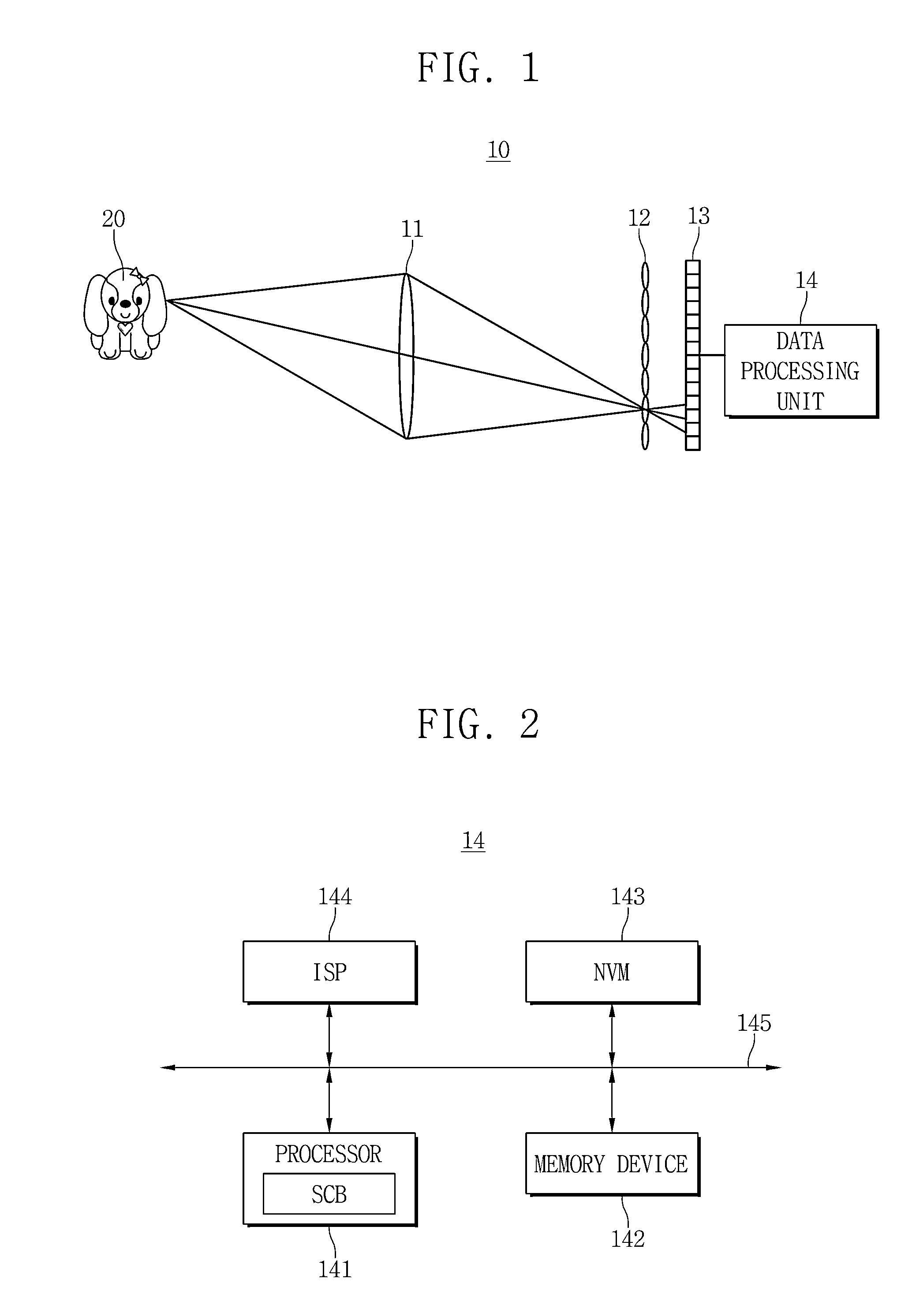
A plenoptic camera device and a shading correction method thereof are provided. The plenoptic camera device includes a processor including a shading correction block configured to determine a four-dimensional axis with respect in a raw image, generate a four-dimensional profile by applying a polynomial fit with respect to the plurality of pixels in the raw image based on the four-dimensional axis, and calculate a gain using the four-dimensional profile and a non-volatile memory device configured to store the gain. Accordingly, the plenoptic camera device can remove a vignetting effect using the gain.

Description

CROSS-REFERENCE TO RELATED APPLICATION[0001]This application claims the benefit of provisional U.S. Application No. 61 / 902,419filed on Nov. 11, 2013, and also claims priority under 35 U.S.C. §119 to Korean Patent Application No. 10-2014-0022128 filed on Feb. 25, 2014, the disclosure of each of which is hereby incorporated by reference in its entirety.BACKGROUND[0002]1. Field[0003]Example embodiments of inventive concepts relate to a plenoptic camera device, and a shading correction method for the camera device.[0004]2. Description of Related Art[0005]A plenoptic camera device or a light field camera device can capture light distribution information and light direction information in a light field. Images obtained by the camera device can be collected with an increased focus depth, or the images can be digitized and the images can be adjusted. In a standard plenoptic camera device, a micro lens array is located in front of an image plane, for example, a photographic plate or a photos...

Claims


Application Information

Patent Timeline
IPC IPC(8): H04N5/235H04N13/02
CPCH04N13/0203H04N5/2354H04N25/61
Inventor KIM, DAE-KWANKIM, TAE-CHANJUNG, JUNG HOON
Owner SAMSUNG ELECTRONICS CO LTD
Learn More