
Coolant Device, Dispenser and Methods Background of the Invention

Active Publication Date: 2015-04-30
ROTHENBERG SARAH
View PDF10 Cites 3 Cited by
  • Summary
  • Abstract
  • Description
  • Claims
  • Application Information

AI Technical Summary

Benefits of technology

This patent is about a coolant device that can be applied to a skin surface to reduce discomfort. The device contains two packets, with the first packet containing a dispersing agent to help the compound spread in the water. When the first packet is ruptured, the compound leaks and comes into contact with urea in the second packet, resulting in a cool surface. The technical effect of this invention is to provide a convenient and effective way to reduce discomfort caused by heat on the skin surface.

Problems solved by technology

Hot flashes can occur at any time and at any place and are a source of considerable discomfort and consternation to many menopausal women.
In the past, many women have resorted to using various forms of medication to lessen the effects of menopause and attendant hot flashes, yet these medications do not provide instant relief for the symptoms of hot flashes, nor do they mask the embarrassment of experiencing the same including experiencing a sudden onset in a public venue.
Since hot flashes can occur at any time and at any place, including in very public venues, it therefore has been a challenge to find a socially acceptable means for reducing the awkward symptoms associated therewith.
While various types of cooling devices have been described previously for this purpose, such devices are quite bulky, and therefore do not provide effective cooling in a discrete manner.

Method used


Image

  • Coolant Device, Dispenser and Methods Background of the Invention
  • Coolant Device, Dispenser and Methods Background of the Invention
  • Coolant Device, Dispenser and Methods Background of the Invention

Examples


example 1

Preparation and Evaluation of An Embodied Coolant Device

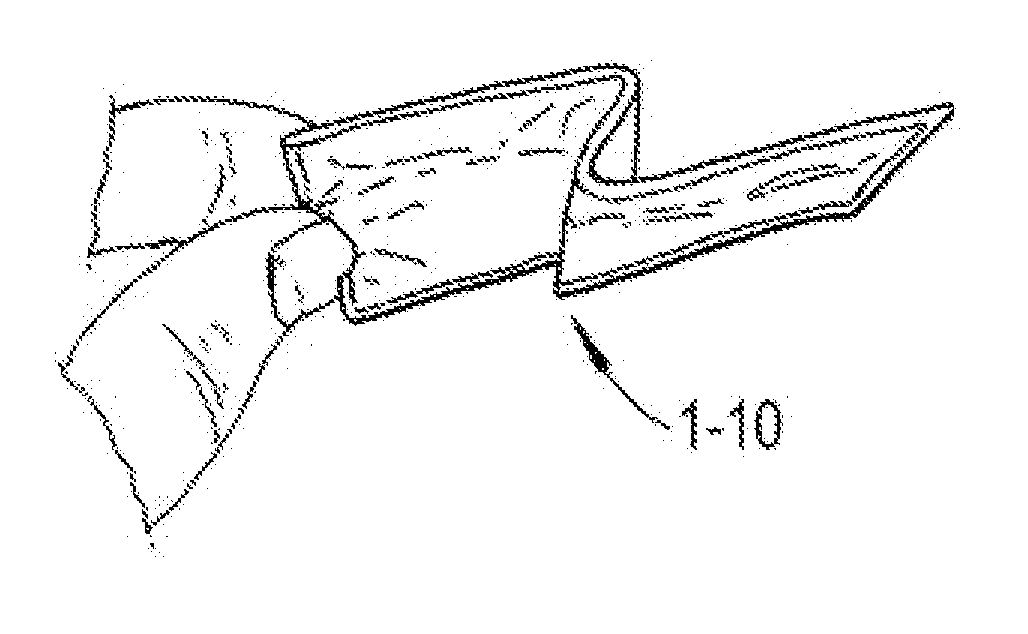
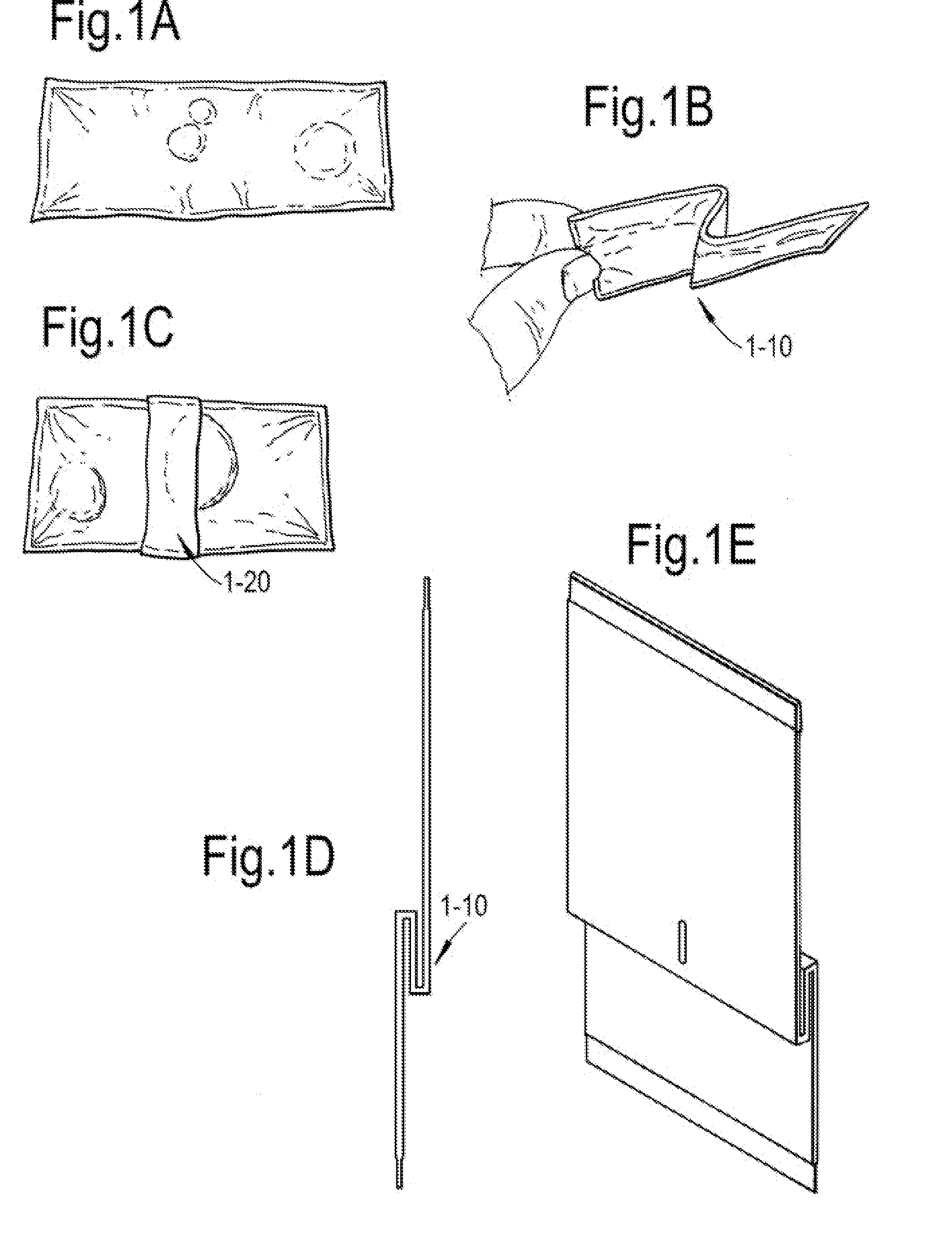
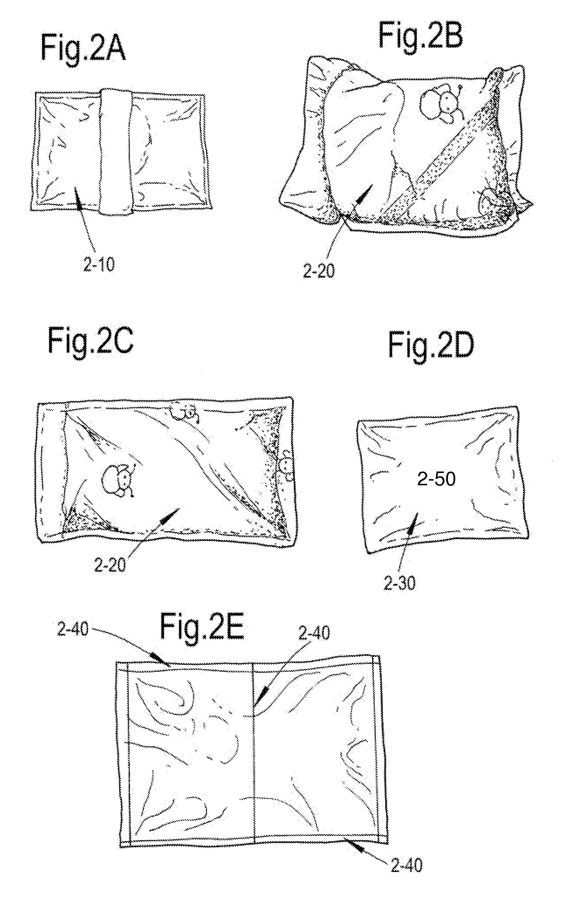
[0097]A sealed packet was made of low density polypropylene (LDPE), which contained 5 and 10 ml of water as follows: the packet was sealed by soldering on three sides and one side was left open (FIG. 1A). 2.5 and 5 ml of water, respectively was introduced into the bags and the bags were oriented to create a center fold 1-10 (FIG. 1B), with spot welding 1-20 conducted at the site of the fold (FIG. 1C). The bags were then sealed with soldering, as well. This packet is referred to herein as the water packet. The dimensions of the components were as follows: the size of the internal water bag was 70×50 mm, the size of external urea-containing bag was 110×60 mm, and the thickness of the final assembled package was approximately 1-10 mm, depending upon the region of cross section.

[0098]A second packet was prepared, into which the water packet 2-10 inserts (FIG. 2). The second packet was comprised of a bi-layer material 2-20. The inte...

example 2

Design of Additional Embodied Coolant Devices

[0107]Example 1 provides a working example of embodied coolant devices. It is of course possible to further engineer the devices.

[0108]In some embodiments, one side or both sides of the coolant device may be further adapted to contain an absorbant material on its exterior, which absorbant material may absorb sweat from the subject to which the device is applied. The purpose of such a material is to provide quick and discreet comfort to the subject, while making use of the coolant activity of the device due to the endothermic reaction occurring in the device interior. The device does not particularly rely upon a wicking effect in order to achieve the cooling effect of the application of the device.

[0109]It is also envisioned that in the preparation of the multi-layered packet containing the water packet and urea located therewithin that the urea is combined in the manufacturing process with a pulp, based on the same principle as the combin...

example 3

Design of Packaging for Embodied Coolant Devices

[0112]Examples 1-2 provide examples of embodied coolant devices. One of the benefits and aims of the subject invention is the creation of a highly discreet cooling device for use by women experiencing hot flashes.

[0113]It is envisioned that the design of the described device allows for very discreet cooling of the skin of the subject alleviating the discomfort of hot flashes, with a material, that for all intents and purposes appears to be a tissue.

[0114]In keeping with the desire for a discreet method of cooling using the device, it is also envisioned that a packaging material for the coolant tissues is constructed, which facilitates the activation of the endothermic reaction as part of the removal of the tissue from the packaging material.

[0115]Referring now to FIG. 3 and representing one embodiment of the invention, the coolant device is assembled such that the water pack 3-20 is located within the laminated packet, which is compris...


PUM


Abstract

This invention provides a thin and discreet coolant device, and single and multiple unit dispenser containers containing the same. The coolant device comprises a first packet being comprised of a waterproof or water-resistant material containing water therewithin and further comprising a fold and further adapted to have a selectively permanent connection between external and internal layers of said fold, such that upon applying a force to laterally extend the ends of said packet, a rupture of said first packet occurs allowing for the leakage of the water contained therewithin. The coolant device further comprises a second packet which encases said first packet, comprising an exterior and interior layer, wherein said interior layer is comprised of an absorbant material and said exterior layer is comprised of a waterproof or water-resistant material and wherein an amount of powdered urea is located within an interior of said second packet. Upon lateral extension of the sides of the second packet, a rupture of said first packet occurs allowing for the leakage of the water contained therewithin and its exposure to said urea located within said second packet, which exposure results in an endothermic reaction resulting in an outer surface of said second packet becoming cooler to the touch than an outer surface temperature prior to said rupture. Use of the coolant devices to provide cooling to a skin surface on demand is described, as well.

Description

BACKGROUND OF THE INVENTION[0001]This invention relates to a coolant device, dispenser apparatus and method for the application of the coolant device to appropriate skin surfaces of the human body to bring relief to the subject. More specifically, the invention relates to the application of cool or cold, discreet, thin tissue-like materials to the skin surface of a subject to alleviate symptoms and discomfort associated with heat, including in women experiencing hot flashes, individuals suffering from minor burns or fever, and other applications.[0002]Hot flashes can occur at any time and at any place and are a source of considerable discomfort and consternation to many menopausal women. In the past, many women have resorted to using various forms of medication to lessen the effects of menopause and attendant hot flashes, yet these medications do not provide instant relief for the symptoms of hot flashes, nor do they mask the embarrassment of experiencing the same including experien...

Claims


Application Information

Patent Timeline
IPC IPC(8): F25D5/02A61F7/10B65D81/32
CPCF25D5/02A61F7/106B65D81/3266A61F2007/0052A61F2007/0269A61F2007/0271
Inventor ROTHENBERG, SARAH
Owner ROTHENBERG SARAH
Learn More