Vacuum piston device

a vacuum piston and vacuum technology, applied in printing and other directions, can solve the problems of affecting the quality of ink, blocking the ink spilling mouth, and oxidizing the ink, and achieve the effects of increasing the sealing contact area, strong strength, and easy loosening

Inactive Publication Date: 2015-04-23
NORTH AMERICA WALES GROUP INT +1
View PDF9 Cites 2 Cited by
  • Summary
  • Abstract
  • Description
  • Claims
  • Application Information

AI Technical Summary

Benefits of technology

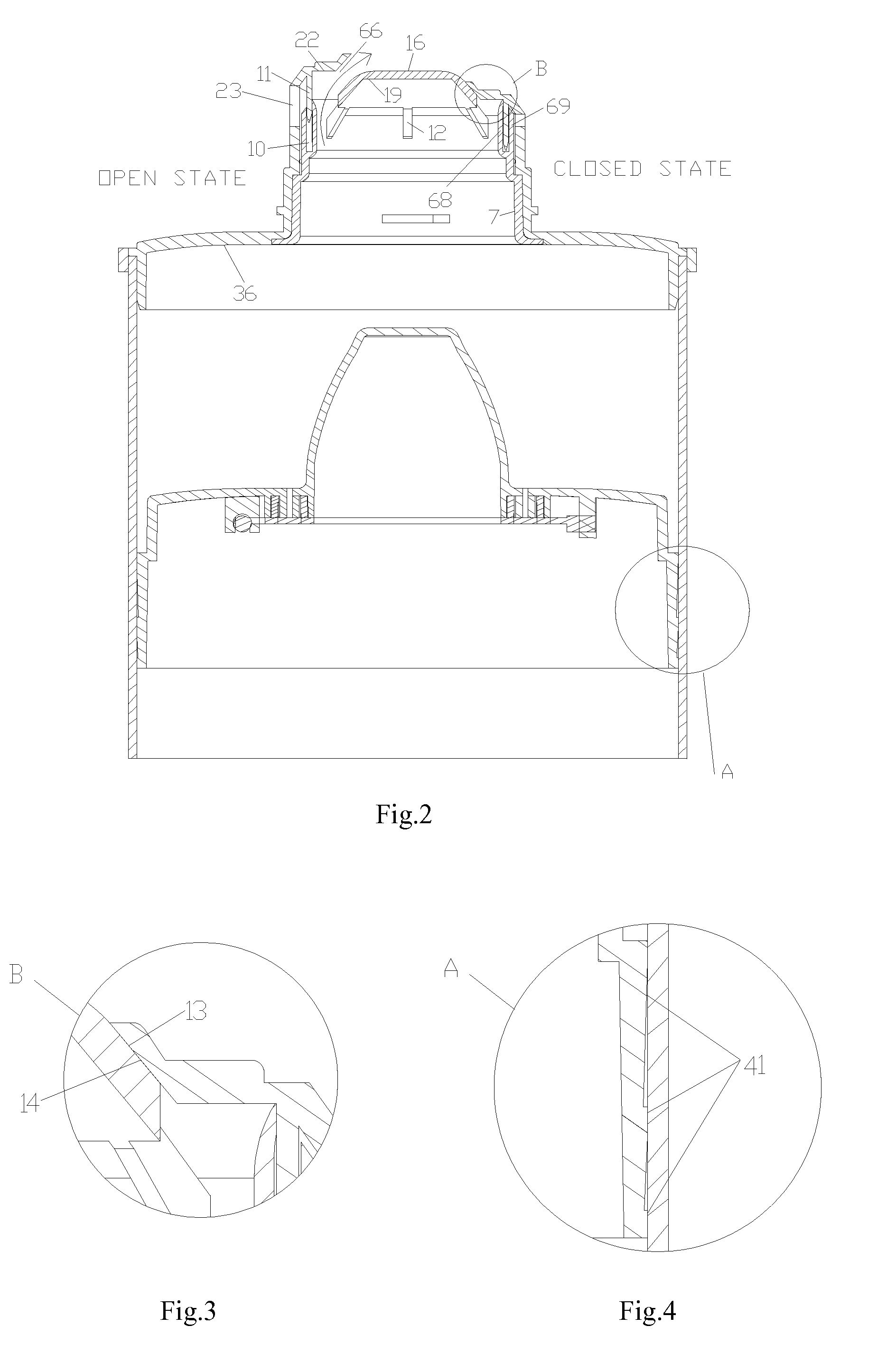
[0030]With the cooperation of two sloping sealing faces in the valve sleeve and valve lid, the sealing contact area is increased drastically, which can be as wide as more than 5 mm, then it accordingly guarantees the real vacuum storing of the ink in the container. In addition, the structure of the ink supply valve, which arranges the valve lid to be connected with the container cylinder directly and embeds the valve sleeve into the valve lid, makes them connected tightly and not easy to become loose.
[0031]Through a lot of experiment, the WI-shaped spring has quite strong strength, is less likely broken, big deflection, little stretch and deflection resistance, and sensitive to stretch and restore. With the WI-shaped spring set between the mouthpiece neck of the valve sleeve and the annular top, the stretch and deflection resistance of the spring get less, the forward movement of the annular top gets longer when supplying ink, which can reach more than 8 mm long, and in turn the annular ink supply opening gets bigger accordingly; as a result, the ink supply becomes smooth and efficient. Likewise, when sealing, the spring tension is strong, and the sealing performance is reliable.
[0032]With a conic bulge and multiple exhaust pores set longitudinally, preferably axially, in the vacuum piston, the air between the piston and the container cylinder can exhaust out completely; accordingly, it can be accomplished to vacuum package ink containers. By setting exhaust tubes and piston lid on the rear end face of the vacuum piston, the sealing at the rear end of the ink container gets more effective; also, the operation becomes more convenient. All of those features at the piston fit the mechanized package. The design of the ink-scraping ring helps the container cylinder to remove residual ink, which increases the usage efficiency of ink.
[0033]It is preferable to use paper as the material of the container cylinder, because the performance of the paper cylinder is more stable and more durable, and thus guarantees the normal cooperation gas between the container cylinder and the piston, which in turn ensure the quality of packaging, storing and supplying ink. Another benefit of using paper is environment-friendly.
[0034]The balance cover is for placing the container upright more steadily. In addition, the inner sealing top of the balance cover and the top wall of the ink supply opening of the valve lid are cooperating tightly with each other, thus, the ink container is sealed one more time and it further ensures the vacuum state.

Problems solved by technology

However, this type of structure allows the air to get into the cylinder through the gap in between the cooperating area of the ink-spilling mouth and the sealing lid; when packaging the piston of the rear end, air can not completely exhaust out of the cylinder and it makes the air stay in the cylinder; as a result, the ink is oxidized, and it in turn influences the quality of the ink, blocks the ink spilling mouth, and eventually disenables the ink' flowing out.
1. A valve sleeve is put over the outer wall of the convex central body, which allows the spherical top of the convex central body to pass through the annular ink-spilling mouth of the top of the valve sleeve, and allows the rim of the valve sleeve to cling to the spherical top of the convex central body. Due to the very little sealing area of this sealing structure between the valve sleeve and the convex central body, which is almost just an annular line and the sealing width is less than 1 mm, once the hot ink gets cooling down after the package procedure, the volume of the ink gets contracting and accordingly produces negative pressure; plus the gravity, it makes it very easy for the air outside to get into the joint of the valve sleeve and the convex central body. Therefore, it causes the ink to get oxidized and get peeling, and accordingly affects the quality of the ink, clogs the ink spilling mouth, and eventually cuts off the ink supply.
2. The connection fashion of the valve sleeve and the convex central body is not tight, easy to be loose, which also makes it for the air to get into the cylinder from the loose cooperation gap.
3. Besides, due to the short stroke, which is less than 3 mm, of the S-shaped wall ribs of this patent in the valve sleeve, the annular ink-spilling mouth, which size depends on the stroke of the S-shaped wall ribs, is just a narrow space. Therefore, it is likely for the ink-spilling mouth to get clogged; the ink pressure gets increased, and then accordingly causes the occurrence of unexpected ink spurt.
4. Also, the structure of the S-shaped wall ribs makes the minimum working pressure for opening the ink spilling mouth to be more than 5 bar, which is too high and likely to cause the piston inside the cylinder to turn sideways and further disenables the ink supply.
5. The connection structure and sealing fashion of the inner wall of the U-profile window and the outer wall of the mouthpiece neck of the convex central body make it likely happen that the ink, under pushing, leaks from the gap between the inner wall of the U-profile window and the outer wall of the mouthpiece neck.
6. The patent is designed only for being used with the plastic cylinder of an ink container. However, the performance and quality of plastic cylinders is not stable, and the cooperation gap between the cylinder and the piston can not be guaranteed very well.
1. The axis of the two exhaust pores is perpendicular to the axis of the plastic cylinder and the air inlets of the exhaust pores are located at the sides of the front end face of the piston. Therefore, the exhaust pores on the sides are not able to expel all air in the container cylinder, and it accordingly causes the ink to be oxidized and peel, and eventually influences the quality.
2. Because there is no any sealing device to cover the air outlets of the exhaust pores on the rear end face of the piston, ink would leak out from them.
3. In addition, the cylindrical bulge of the piston and the vertical ink-guiding groove on the surface of the cylindrical bulge hinder the air from exhausting. When the piston is pushed by an outer force to move along the inner wall of the cylinder, because the top of the cylindrical bulge impacts the ink and produces central whirlpools bigger than the cylindrical bulge itself, the ink under the impact will move toward the peripheral area of the bulge; therefore, the air in the cylinder will rapidly flow to and gather around the cylindrical bulge and the vertical ink-guiding groove, and can not exhaust out of the cylinder. When the bulge entirely gets into the ink and the ink covers the frontal end face of the piston, there is still air staying around the cylindrical bulge and at the vertical ink-guiding groove, which will make the ink to peel and dry, and accordingly affect the ink quality directly.
4. The container cylinder is also made of plastic. The conventional plastic cylinder tends to expand and contract more easily as the temperature changes; thus, it is easier to deform and crack. In addition, the taper degree generated during the manufacture might cause the inner diameter of the container cylinder with a smaller front part and a bigger rear part, which will influence the cooperation gap between the container cylinder and the vacuum piston. When the cooperation is looser, the piston might separate from the cylinder, while the cooperation is tighter, the pressure of supplying ink increases, and in turn causes higher pressure in the cylinder, then the piston will be stuck in the cylinder and it finally fails to supply the ink.

Method used


Image

  • Vacuum piston device
  • Vacuum piston device
  • Vacuum piston device

Examples


Embodiment Construction

[0050]In the following detailed description of the embodiments, reference is made to the accompanying drawings.

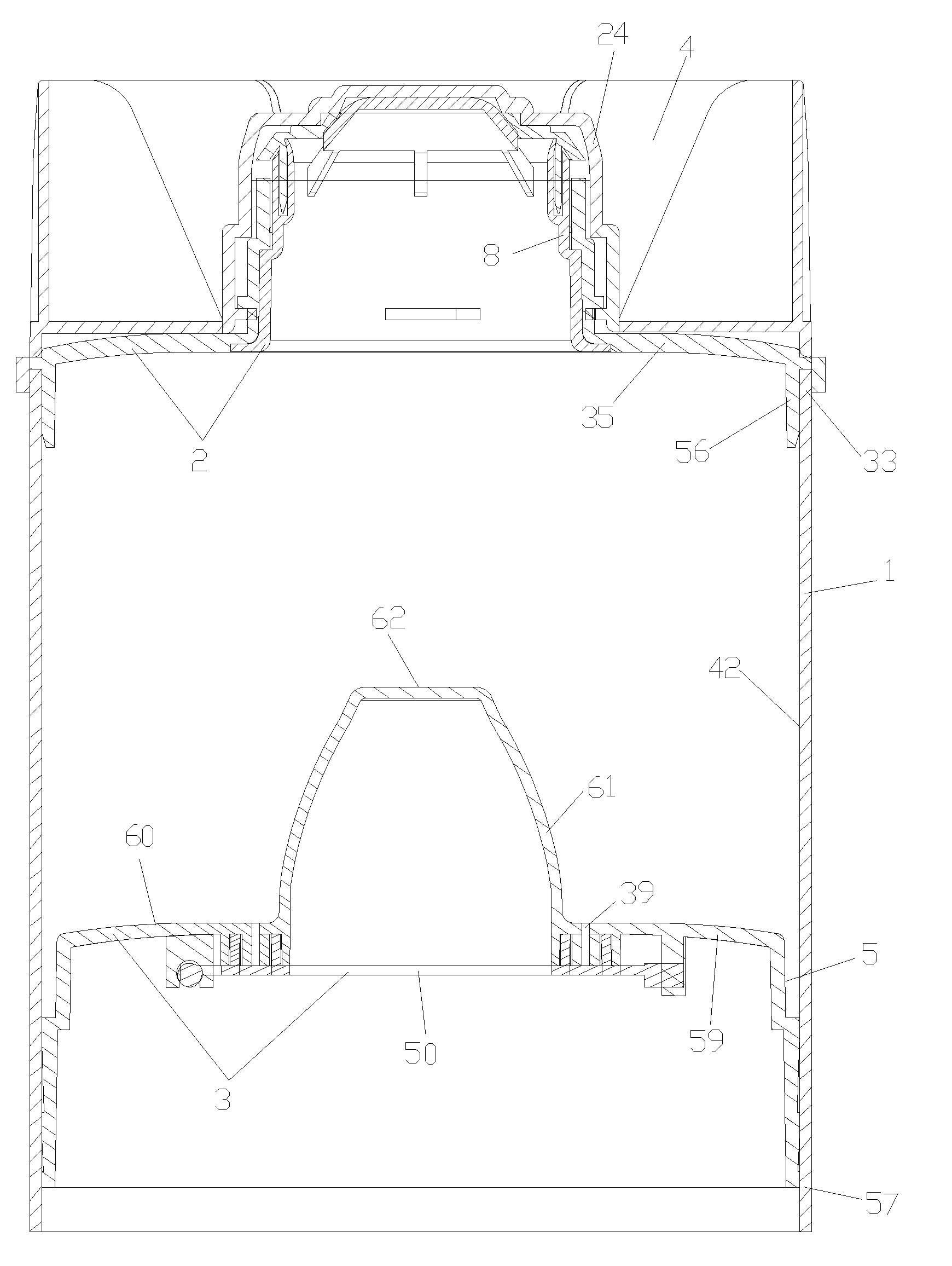
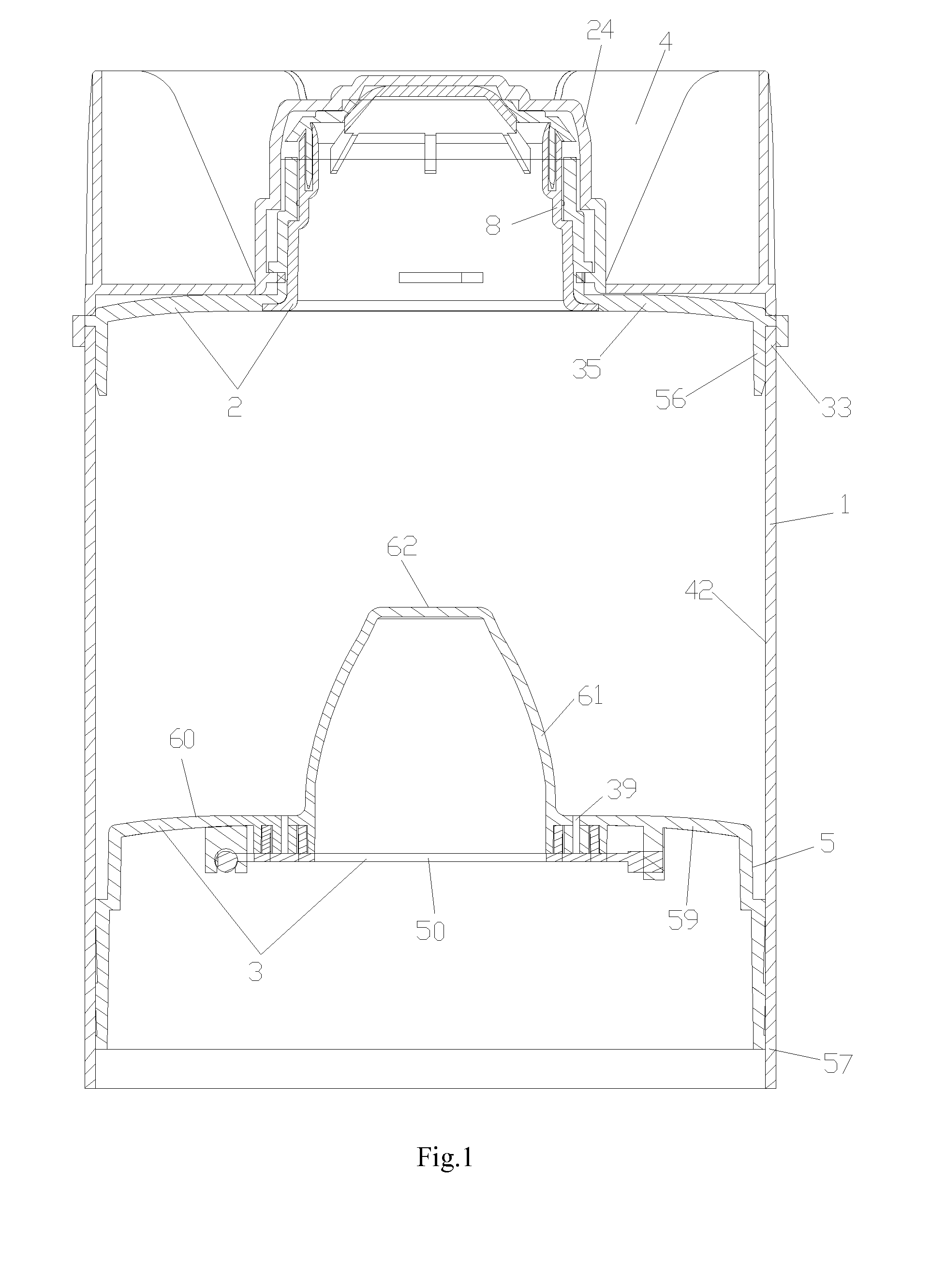
[0051]Referring to FIG. 1, the automatic vacuum ink container of the present invention comprises a container cylinder 1, an ink supply valve 2, a vacuum piston 3 and a balance cover 4. The vacuum piston 3 is located within the container cylinder 1 and at the rear end of the ink container for sealing the ink container. The ink supply valve 2 is located at the frontal end of the ink container. The balance cover 4 is mounted on the ink supply valve.

[0052]The container cylinder 1 can be made of different materials. The embodiment uses paper as the material, because the performance of the container cylinder made of paper is more stable and more durable. In addition, paper-made cylinder can guarantee better normal gap between the inner radiuses and the vacuum piston, which is helpful for the ink quality during packaging, sealing and storing. Environment-friendly is also another a...


PUM


Abstract

A vacuum piston device used in ink supply system, includes: a cylindrical piston body; a conic bulge set at a central area of a frontal end face of the cylindrical piston body; and a piston lid mounted at a rear end face of the cylindrical piston body; at least one exhaust pore is set on the frontal end face around the conic bulge and all the way goes through to the rear end face; an annular groove is formed on the rear end face in such a manner that inner and outer walls of the annular groove project out from the rear end face; the piston lid is for covering the annular groove, and eventually for sealing the whole piston.

Description

CROSS REFERENCE OF RELATED APPLICATION[0001]This is a Continuation-In-Parts application of U.S. reissue patent application Ser. No. 14 / 060,614, filed on Oct. 23, 2013, which had a patent number of U.S. Pat. No. 8,430,488, issued on Apr. 30, 2013, and an application Ser. No. 12 / 979,244, filed on Dec. 27, 2010.BACKGROUND[0002]1. Field of the Invention[0003]The present invention relates to an automatic vacuum ink container, more specifically, to the automatic vacuum ink container that can be applied in mechanized ink-filling production and vacuum package and store, and used with the automatic ink supply equipment, and to its ink supply valve device and vacuum piston device.[0004]2. Description of Related Arts[0005]In the printing field, the modern printing machine has gradually started to use the automatic ink supply technology. The plastic ink container, which is used with the automatic ink supply equipment, is a cylinder. There is a piston provided at its rear end and an ink-spilling...

Claims


Application Information

Patent Timeline
Patent Type & Authority Applications(United States)
IPC IPC(8): B41J2/175
CPCB41J2/17513B41J2/17553B41J2/17556B41J2/17596
Inventor TAN, CIYUAN
Owner NORTH AMERICA WALES GROUP INT
Why Eureka
Try Eureka