
Transparent Ice Maker

a transparent ice maker and transparent technology, applied in the field of transparent ice makers, can solve the problems of limited ability to produce clear ice cubes, specific construction materials, and inconvenient use, and achieve the effect of reducing the surface area to volume ratio and preventing additional solid ice growth

Inactive Publication Date: 2015-04-23
PAPALIA ROCCO
View PDF3 Cites 35 Cited by
  • Summary
  • Abstract
  • Description
  • Claims
  • Application Information

AI Technical Summary

Benefits of technology

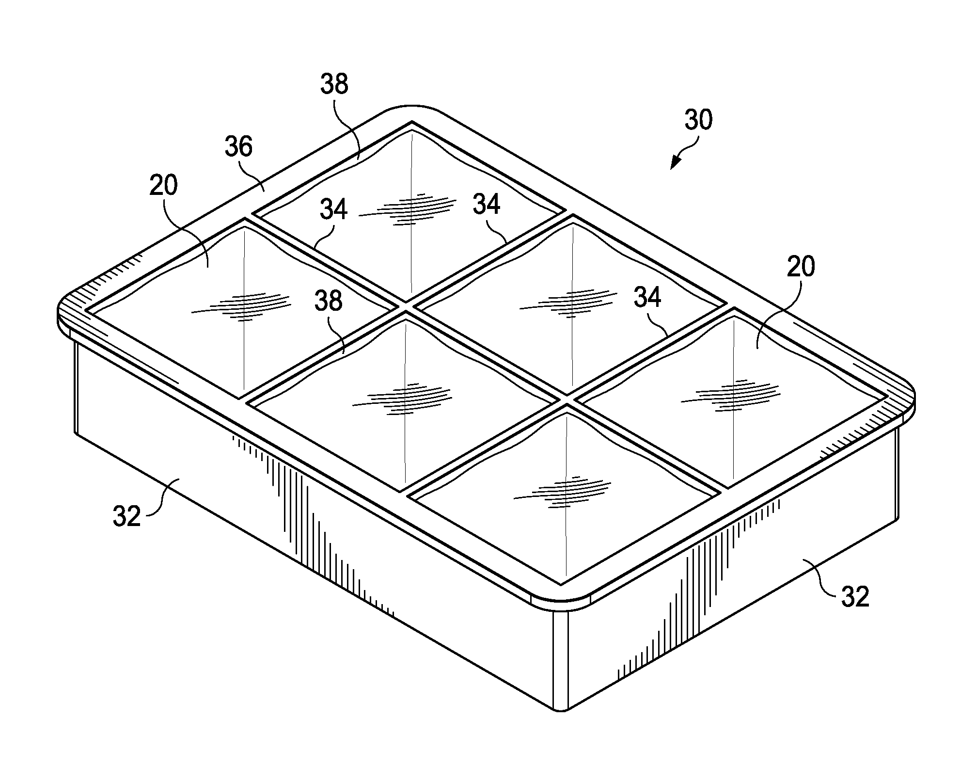
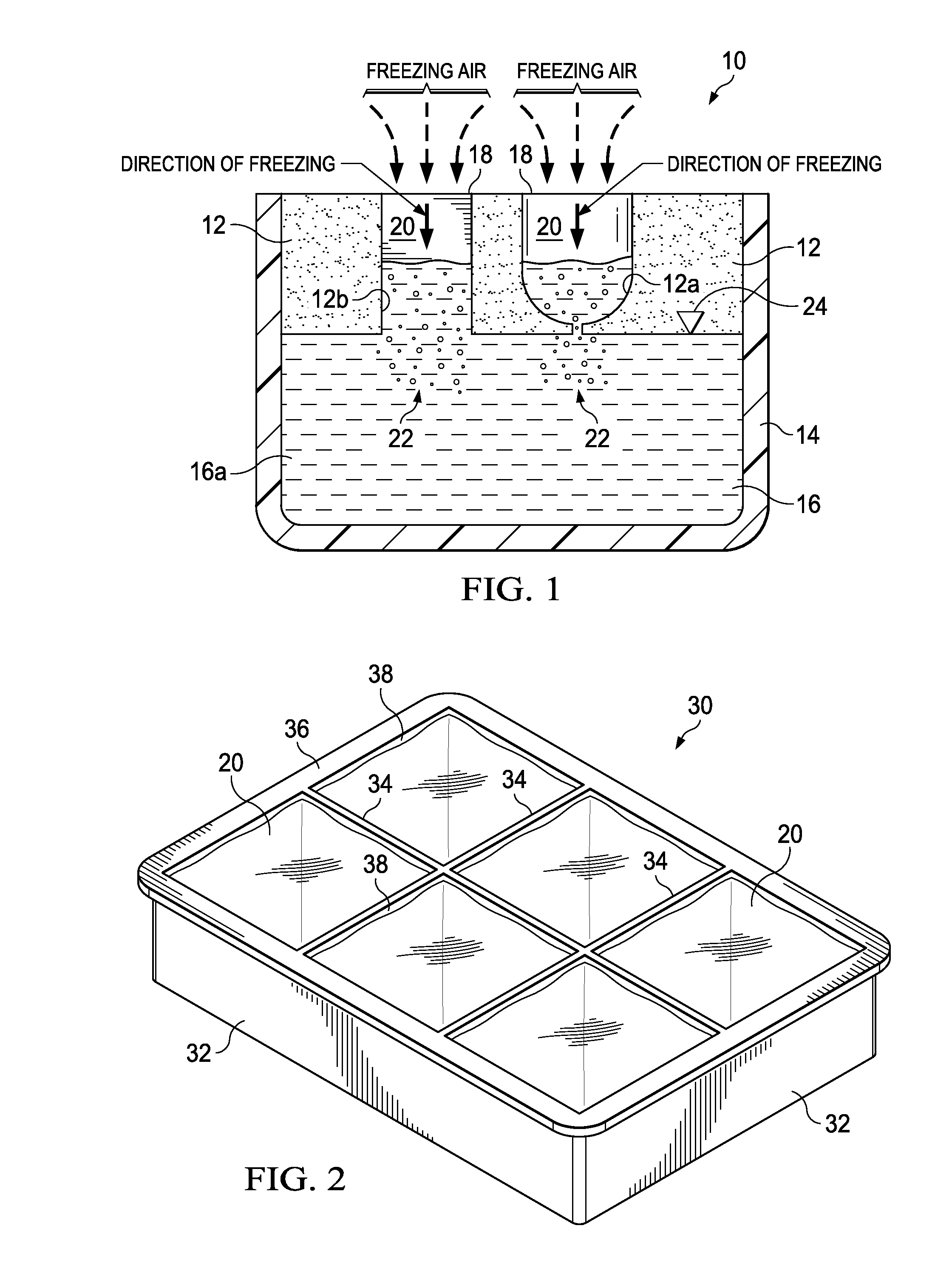
The present invention provides an apparatus and method for forming clear or transparent ice in a variety of geometric shapes. The apparatus includes an insulated ice mold form containing one or more mold cells, each mold cell with an open top, open bottom, and formed insulated side walls that is suspended over a liquid water reservoir surrounded by an insulated container. The liquid water reservoir acts as an impurity sink into which impurities and gases contained in the freezing water contained in each mold cell are driven as ice crystals form and ice growth occurs in each cell in a vertical downward direction. The liquid water reservoir also acts as a heat sink to resist freezing while the ice shapes in the mold cells are freezing into a solid phase above the ice-reservoir water interface during the ice shape formation process. The apparatus is easy to use, with no need for mechanical cutting or thermoelectric separation equipment to separate the ice mold form from the insulated container. The clear ice shapes can be easily ejected by hand from the individual mold cells and immediately used for cooling purposes or placed in a freezer for storage. The apparatus and method can be used in a variety of geometric shapes, such as cubic, conical, square, spherical, hemi-spherical, or other ice shapes as desired.

Problems solved by technology

Impurities and gases contained within the water to be frozen are trapped in the solidified ice cube during the freezing process, commonly near the center and / or the bottom surface of the ice cube, due to their inability to escape as a result of the freezing liquid to solid phase change of the ice cube surfaces.
The method and apparatus disclosed in U.S. Pat. No. 6,357,720 is also limited in its ability to produce clear ice cubes in that the gases vented during the freezing process must be diffused through the permeable sidewalls and the mold bottom at a faster rate than the liquid-to-solid phase change rate occurring in the ice mold.
However, the suspended and dissolved solids and liquids in the water freezing in the molds are not removed or liberated and remain in the resulting ice cubes.
Another drawback of these known apparatii and methods for producing clear ice concerns their requirement of electro-mechanical energy inputs and assemblies, and / or specific construction materials (e.g. air permeable) that may only be formed and produced using technical construction methods and equipment in order to function and produce clear ice.
Moreover, they fail to produce a clear ice product as they are generally focused and drawn to the removal of a specific contaminant, such as gas bubbles or suspended solids, versus the removal of the combination of suspended and dissolved liquids, solids and gases which exist in unfrozen water and prevent the formation of clear ice.

Method used


Image

  • Transparent Ice Maker
  • Transparent Ice Maker
  • Transparent Ice Maker

Examples


Embodiment Construction

[0020]Certain terminology is used herein for convenience only and is not to be taken as a limitation on the present invention. Relative language used herein is best understood with reference to the drawings, in which like numerals are used to identify like or similar items. Further, in the drawings, certain features may be shown in somewhat schematic form.

[0021]Without being bound by theory, the inventive apparatus and method described herein provide for the production of substantially clear, if not transparent, ice shapes by taking advantage of the thermodynamic differential in the rate of heat loss resulting from different SA / V ratios between an ice mold shape and a liquid water reservoir as described in detail below. Generally, an object or shape gains or loses heat through its surface area, so the larger the surface area of the object or shape the faster the associated rate of heat loss or heat gain. Likewise, an object or shape with a smaller surface area will experience a slow...


PUM


Abstract

The present invention provides an apparatus and method for producing substantially clear ice in a variety of desired shapes. An insulated ice mold form containing one or more mold cells is suspended over a liquid water reservoir contained in an insulated container. Each ice mold cell is exposed to freezing air resulting in the formation of ice in each mold cell with ice formation progressing from the top to the bottom of each ice mold cell. A liquid water reservoir below each ice mold cell serves as an impurity sink into which impurities and gases are driven as ice crystals form in each ice mold cell and as a heat sink to substantially arrest ice shape growth beyond the bottom of each ice mold cell at or near the ice-reservoir water interface.

Description

CROSS-REFERENCE TO RELATED APPLICATIONS[0001]This application claims the benefit of and priority to copending U.S. provisional patent application, Ser. No. 61 / 892,679, filed on Oct. 18, 2013 with the United States Patent & Trademark Office the complete disclosure of which is incorporated herein by reference.BACKGROUND OF THE INVENTION[0002]The present invention relates generally to an improved apparatus and method for making clear or transparent ice, and more specifically, to an apparatus and method for making clear or transparent ice in a variety of geometric shapes and which can be implemented in commonly available refrigeration / freezer equipment.[0003]Typical household and commercial refrigeration systems include separate refrigerator and freezing compartments. Ice cubes may be formed manually or automatically in various conventionally known manners utilizing the freezing compartment of such refrigeration and freezing equipment. As is commonly known, making ice typically involves...

Claims


Application Information

Patent Timeline
IPC IPC(8): F25C1/18F25C1/04
CPCF25C1/04F25C1/18F25C2500/02Y02P60/85F25C1/24
Inventor PAPALIA, ROCCO
Owner PAPALIA ROCCO
Learn More