Portable electronic apparatus having vision care functions
- Summary
- Abstract
- Description
- Claims
- Application Information
AI Technical Summary
Benefits of technology
Problems solved by technology
Method used
Image
Examples
embodiment 1-1
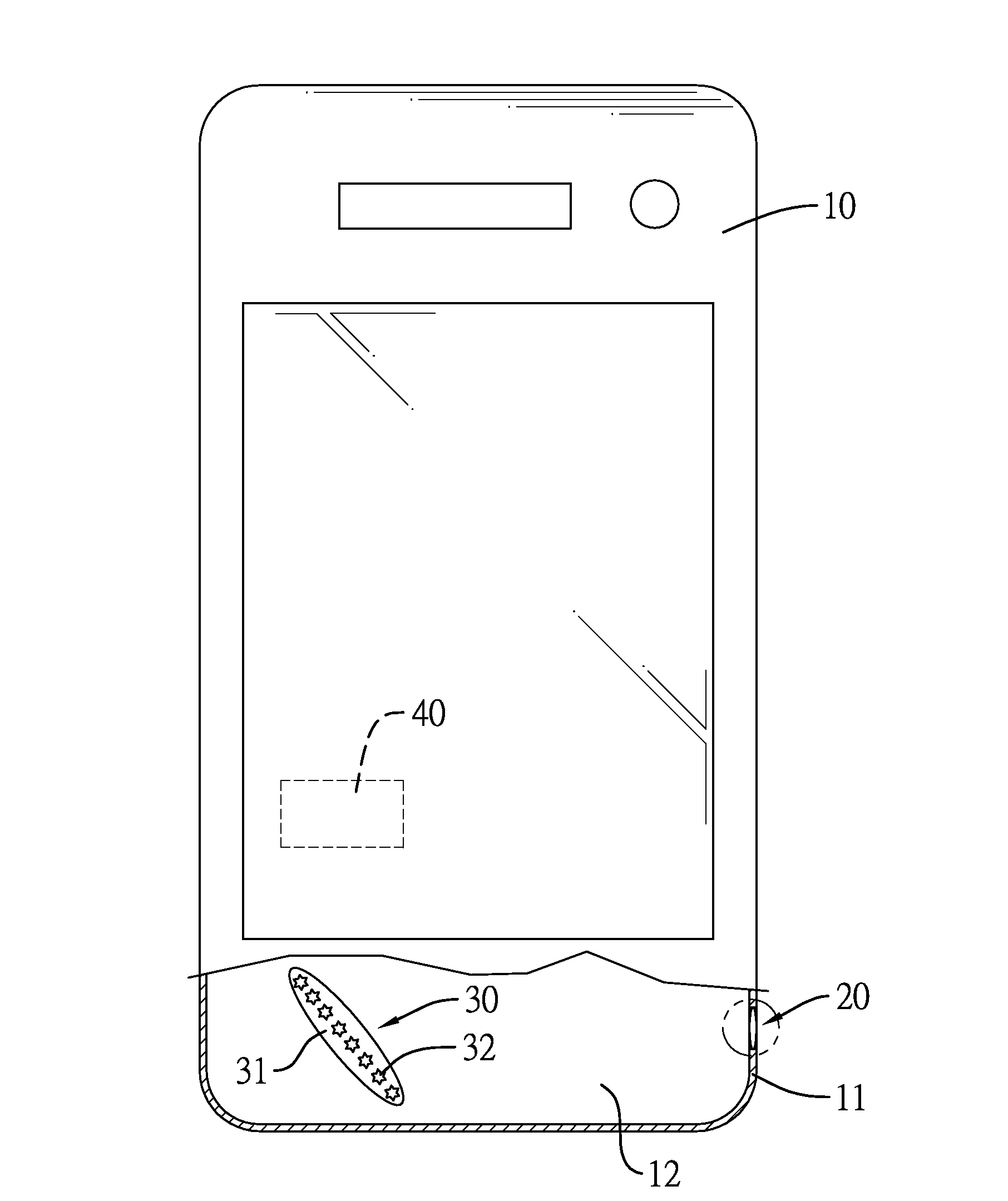
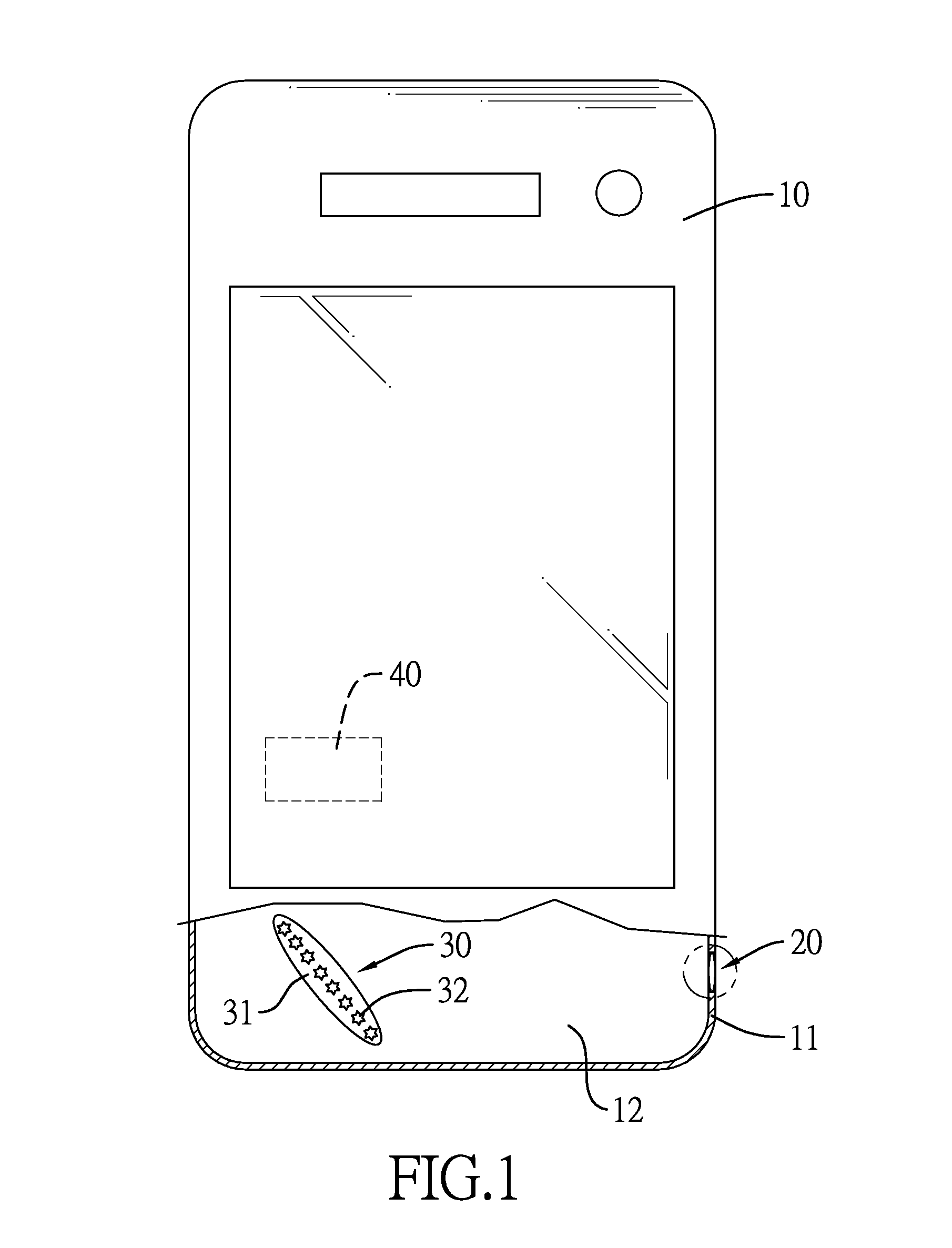
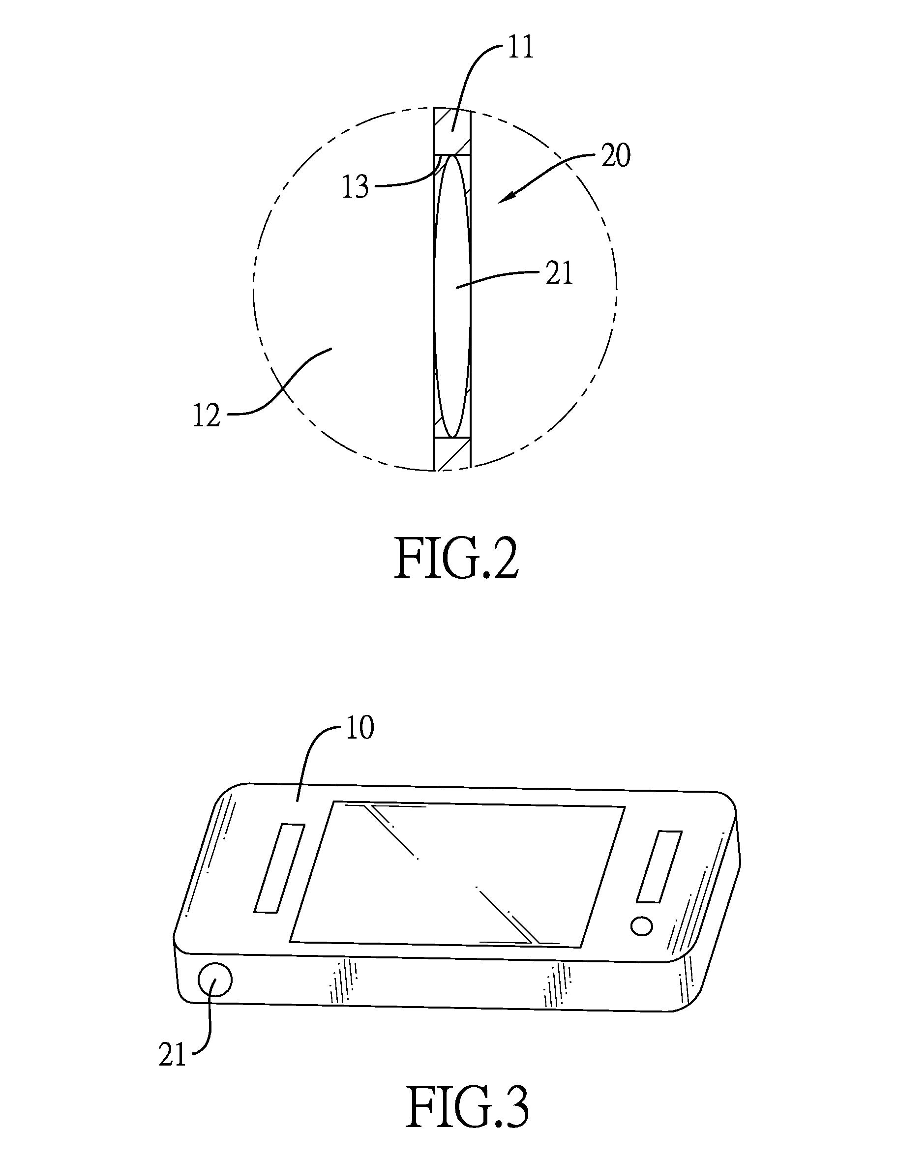
[0050]With reference to FIG. 4, for example, the focal length (f) of the convex lens 21 is 0.4 centimeters. With reference to FIGS. 5a and 5b, the display module 30 is mounted obliquely from the lens assembly 20. Multiple LEDs as the light sources 32 are mounted on the carrier 31 along a virtual straight line. Each activated light source 32 as a light spot is illustrated in FIGS. 5a and 5b, the rest of the light sources32 that are not activated are omitted. User's eyes 50 beside the lens assembly 20 can see the display module 30 through the lens assembly 20. When the light sources 32 are alternately activated, the display module 30 creates an object image of a moving light spot, such that the user can observe the object image of the moving light spot. When the object length (u) is 0.4 centimeters, the image length (v) approximates an infinite value. When the object length (u) is 0.3900 centimeters, the image length is 15.60 centimeters. The variations between the different object le...
embodiment 1-2
[0052]Based on the disclosure of the embodiment 1-1, the only difference between embodiments 1-2 and 1-1 is that the focal length (f) of the convex lens 21 in the embodiment 1-2 is 40 centimeters. When the object length (u) is 40 centimeters, the image length (v) approximates an infinite value. When the object length (u) is 11 centimeters, the image length (v) is 15.17 centimeters. Table 2 disclosed below shows relationships of different focal lengths, the object lengths, and the image lengths of this embodiment.
TABLE 2Focal length (cm)Object length (cm)Image length (cm)4011.0−15.174039.5−31604040.0∞
embodiment 2-1
[0053]With reference to FIG. 4, for example, the focal length (f) of the convex lens 21 is 10 centimeters. The display module 30 is mounted in parallel with the lens assembly 20. With reference to FIGS. 6a and 6b, the carrier 31 of the display module 30 can be, but is not limited to, a circular panel. The multiple light sources 32 of the lens assembly 20 can be LEDs to form an LED array. Each activated light source 32 as a light spot is illustrated in FIGS. 6a and 6b, the rest of the light sources 32 that are not activated are omitted. When the object length (u) is 6.67 centimeters, the image length (v) is 20.03 centimeters. When the light sources 32 are alternately and sequentially activated in counterclockwise direction along an edge of the carrier 31, the user can observe an object image of the moving light spot created by the lens assembly 20. The eyes are rolled to trace the moving light spot to exercise the extraocular muscles of the eyes. Table 3 disclosed below shows relatio...
PUM
 Abstract
Description
Claims
Application Information
 - R&D
- Intellectual Property
- Life Sciences
- Materials
- Tech Scout
- Unparalleled Data Quality
- Higher Quality Content
- 60% Fewer Hallucinations
Browse by: Latest US Patents, China's latest patents, Technical Efficacy Thesaurus, Application Domain, Technology Topic, Popular Technical Reports.
© 2025 PatSnap. All rights reserved.Legal|Privacy policy|Modern Slavery Act Transparency Statement|Sitemap|About US| Contact US: help@patsnap.com


