
Fitting Contact Lenses for Irregular Corneas

a technology of contact lenses and irregular corneas, applied in the field of soft contact lens fitting, can solve the problems of corneal deviance, corneal irregularity, and impaired vision of subjects with irregular corneas

Active Publication Date: 2013-02-21
CONTACT LENS PRECISION LAB
View PDF0 Cites 1 Cited by
  • Summary
  • Abstract
  • Description
  • Claims
  • Application Information

AI Technical Summary

Benefits of technology

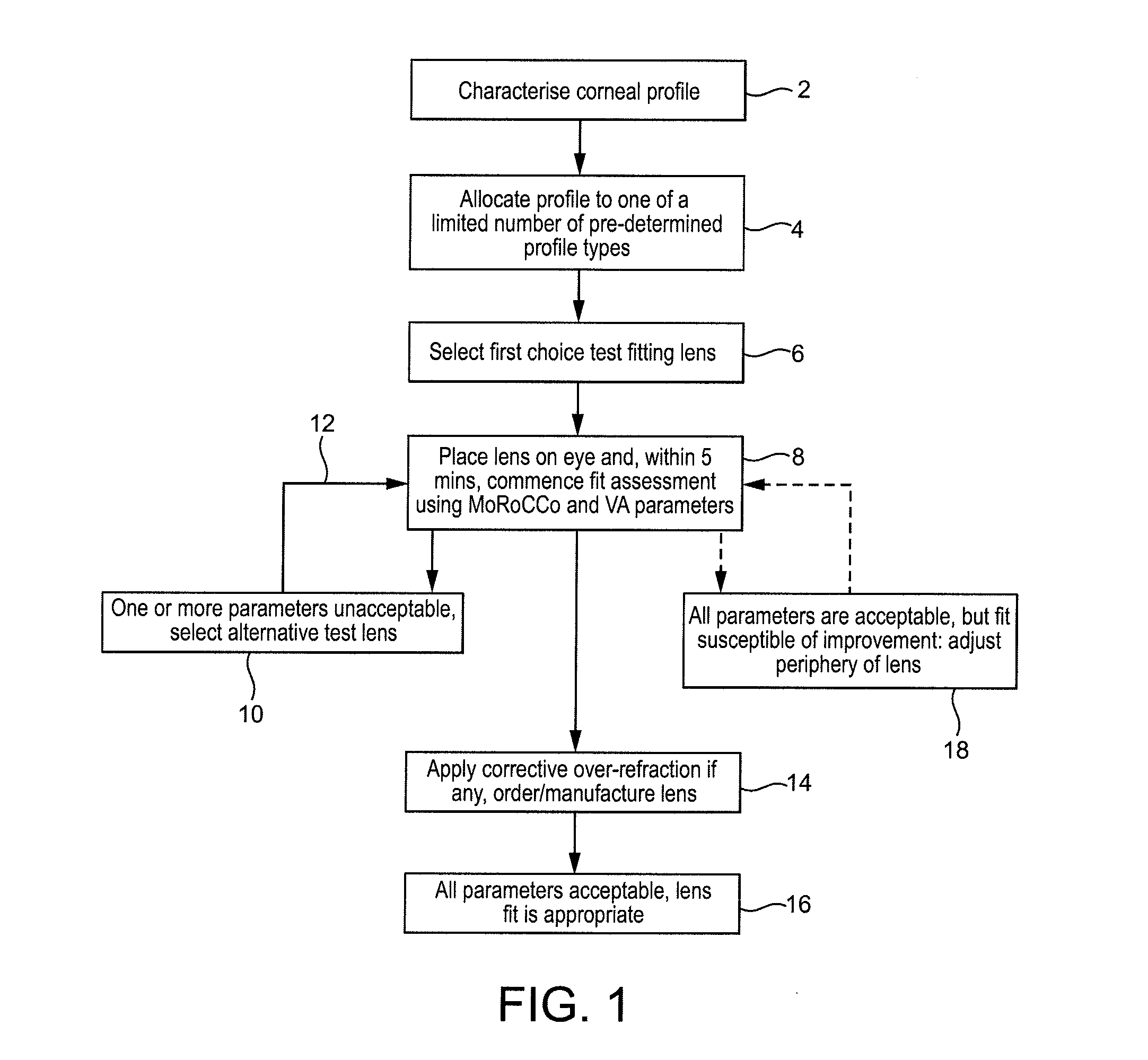
[0025]The method of the invention increases the chance that the practitioner will select the test fitting lens, typically from a pre-supplied test lens kit, most appropriate to the corneal profile of the subject, and thus achieve the best fit as efficiently as possible and, if this is not achieved with the first lens, will tend to reduce the amount of trial and error required to identify an appropriately-fitting lens.
[0039]Once the desired curvature(s) for the periphery of the lens has been ascertained, a contact lens can be manufactured according to the required characteristics, and incorporating any over-refraction needed to correct refractive vision defects in the subject.

Problems solved by technology

However, in some subjects the cornea deviates substantially from the ideal sphere and such corneas are said to be irregular.
Subjects with irregular shaped corneas will suffer impaired vision due to the irregular astigmatism and optical aberrations arising from the corneal distortion, quite apart from any other vision defects they may also have.
However, it is not possible to use the fluorescein technique to assist in fitting soft contact lenses because, inter alia, soft contact lenses drape more to the corneal shape resulting in a uniform tear film.
Due to fluid take up of soft lenses, high molecular weight fluorescein derivatives have to be used with these lenses but even so, very little information as to fit can be deduced from the appearance of the fluorescing tear film.
Accordingly, there is a high degree of skill required to ensure a soft contact lens achieves a good fit on an irregular cornea, and a significant amount of trial and error is required.

Method used


Image

  • Fitting Contact Lenses for Irregular Corneas
  • Fitting Contact Lenses for Irregular Corneas
  • Fitting Contact Lenses for Irregular Corneas

Examples


example 2

Subject with Central Keratoconus

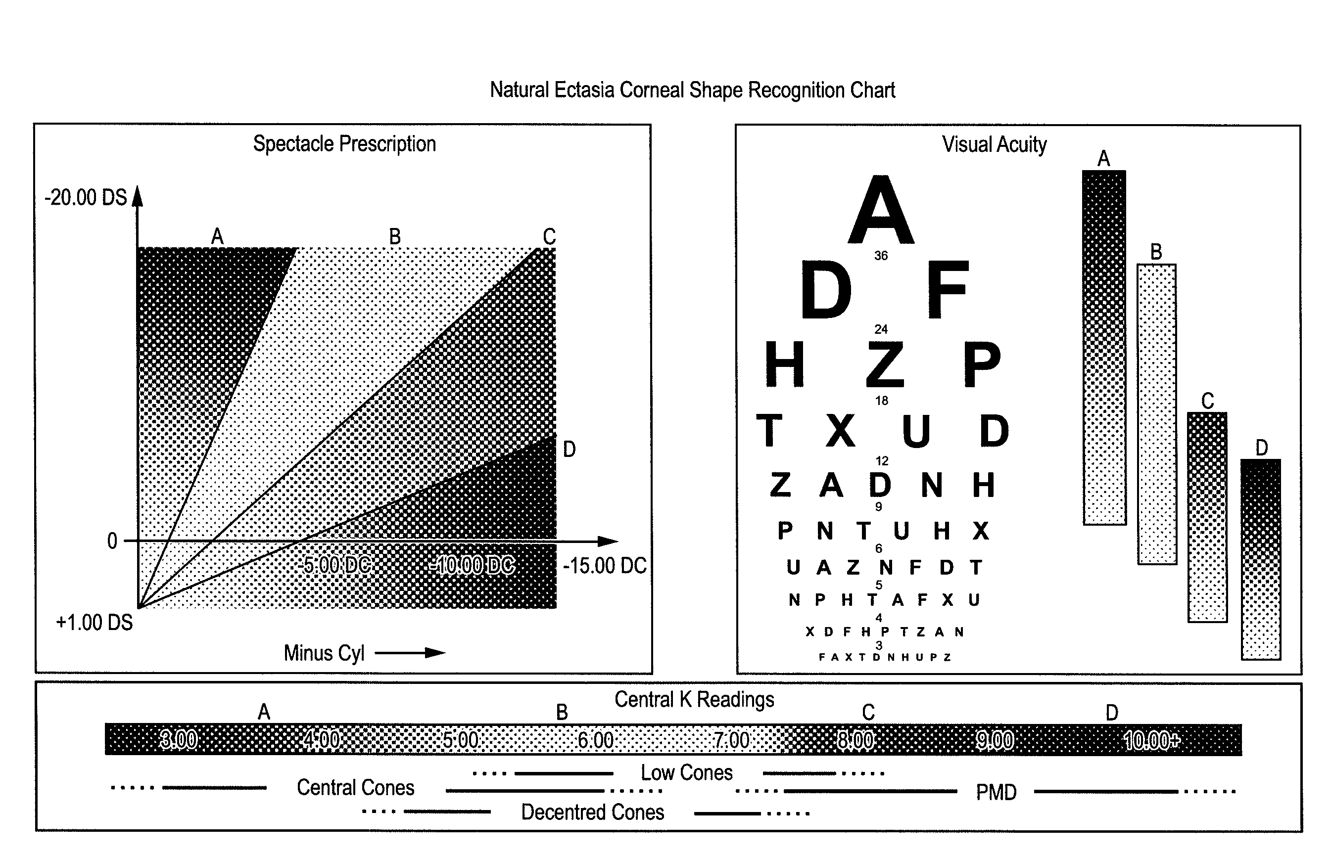
[0109]Identifying Corneal Shape[0110]Spectacle Rx+0.25 / −2.75×10³ VA 6 / 15[0111]Sim Ks: 7.32 / 6.78[0112]Steepest curvature (Inferior): 6.34 mm radius[0113]Flattest curvature: 7.93 mm radius[0114]Curvature of “green area” on topography: 7.30[0115]Corneal Astigmatistm: −4.98×141@ 3 mm[0116]−3.48×143 @ 5 mm

Corneal Shape Recognition Chart

[0117]This cornea demonstrated reasonably normal K readings with a low spectacle Rx but with the central acuity affected significantly. This is typical of mild central ectasias, as any distortion on the visual axis impacts on VA.

[0118]The corneal topography, analysed using a corneal topographer instrument, had a pattern reminiscent of low cones / PMD but the central location of a steep area confirmed keratoconus. The curvature of the “green” area and the flattest curvature value showed that this cornea had a relatively steep periphery.

First Choice Lens

[0119]Even though this was a case of mild keratoconus, the cornea had a rela...

example 3

Subject with Decentred Cone

History

[0143]Subject diagnosed with keratoconus 14 years previously and had worn RGP lenses since. (VA this eye 6 / 12). The cornea had central scarring and significant staining with fluoresein. Due to the current discomfort, the patient elected to go without a lens until the cornea had demoulded.

Identifying Corneal Shape

[0144]Spectacle Rx: +1.25 / −6.25×50 VA 6 / 15[0145]Sim Ks: 6.13 / 5.39[0146]Steepest curvature: 4.75 mm radius[0147]Flattest curvature: 9.30 mm radius[0148]Curvature of “green area” on topography: 7.50

Corneal Astigmatism: −7.58 D ax 11 at 3 mm

[0149]−6.56 D ax 41 at 5 mm

Corneal Shape Recognition Chart

[0150]In this case, the spectacle refraction had been affected by central scarring and thus the normal relationship between refraction and corneal shape had been changed. Decentred cones often demonstrate oblique axes, which can be a useful clue if topography is not available. This cornea demonstrated a very flat periphery on topography but this may n...

example 4

Subject with Low Cone

History

[0184]Subject diagnosed with Pellucid Marginal Degeneration 4 years previously and had a Corneal Collagen Cross linking (CXL) procedure 6 months previously. He had not used his RGP lenses since then and now wished to be refitted into soft lenses.

Identifying Corneal Shape

[0185]Spectacle Rx:+1.50 / −8.00×120 VA 6 / 19[0186]Sim Ks: 6.55 / 5.68[0187]Steepest curvature (Inf): 6.61 mm radius[0188]Flattest curvature: 8.80 mm radius[0189]Curvature of “green area” on topography: 7.00[0190]Corneal Astigmatism: −7.81×128 @ 3 mm[0191]−6.80×131 @ 5 mm

Corneal Shape Recognition Chart

[0192]Although the topography map showed a classical PMD “crabs claw” pattern and the Spectacle Acuity also indicated this condition, in this case, the steepest area of curvature was relatively high and was thus better described as a low cone. A “Low cone” condition was also suggested from the central K readings and the poor Spectacle Acuity, which was caused by the rapid changes of curvature with...


PUM


Abstract

Disclosed is a method of determining an appropriately shaped soft contact lens for a subject with an irregular cornea, the method comprising the steps of: inferring or deducing the profile of the cornea over at least a portion thereof: selecting a first choice fitting lens, the selection being based on the profile of the cornea obtained in the preceding step; assessing the fit of the contact lens to the cornea, by investigating each of the following parameters; (i) translational movement of the lens on eye; (ii) rotation of the lens on eye; (iii) centration of the lens on eye; (iv) the perceived comfort of the lens for the subject; (v) the visual acuity of the subject when wearing the lens; and adjusting the choice of fitting lens, if required, according to the assessment and reiterating until a desired fit of lens to the cornea has been obtained.

Description

FIELD OF THE INVENTION[0001]This invention relates to a method of fitting a soft contact lens for a subject with an irregular cornea.BACKGROUND OF THE INVENTION[0002]In most human subjects, the surface of the cornea is a good approximation to a portion of a sphere. However, in some subjects the cornea deviates substantially from the ideal sphere and such corneas are said to be irregular. Irregular corneas may be a result of surgery or grafting, or may arise from natural ectasia (a thinning of the cornea that results in some areas being steeper than others), such as in keratoconus, which affects at least 1 in 2000 of the population.[0003]Subjects with irregular shaped corneas will suffer impaired vision due to the irregular astigmatism and optical aberrations arising from the corneal distortion, quite apart from any other vision defects they may also have. Traditionally, such visual defects in subjects with irregular corneas have been corrected, or at least ameliorated, using rigid c...

Claims


Application Information

Patent Timeline
Patent Type & Authority Applications(United States)
IPC IPC(8): A61B3/107
CPCG02C7/047G02C7/024G02C2200/28
Inventor MYHILL, JOAN CHRISTINEWHITE, LYNN
Owner CONTACT LENS PRECISION LAB
Learn More