Imaging device, image reading apparatus, image forming apparatus, and image reading method

a technology of image reading and reading apparatus, applied in the direction of electrical equipment, pictoral communication, etc., can solve the problems of fixed pattern noise, correction error between colors, and deterioration of image quality read by the cmos image sensor

Active Publication Date: 2015-04-09
RICOH KK
View PDF2 Cites 41 Cited by
  • Summary
  • Abstract
  • Description
  • Claims
  • Application Information

AI Technical Summary

Benefits of technology

[0010]It is an object of the present invention to at least partially solve the problems in the conventional technology.

Problems solved by technology

There are factors to deteriorate the quality of the image read by the CMOS image sensor, and a known factor is fixed pattern noise that occurs due to variation of each pixel.
Since the area sensor in the past cannot handle the data of multiple colors synthesized for the same pixel position by the same black correction circuits, there has been a problem that a correction error occurs between colors due to the variation of black correction circuits.

Method used


Image

  • Imaging device, image reading apparatus, image forming apparatus, and image reading method
  • Imaging device, image reading apparatus, image forming apparatus, and image reading method
  • Imaging device, image reading apparatus, image forming apparatus, and image reading method

Examples


embodiments

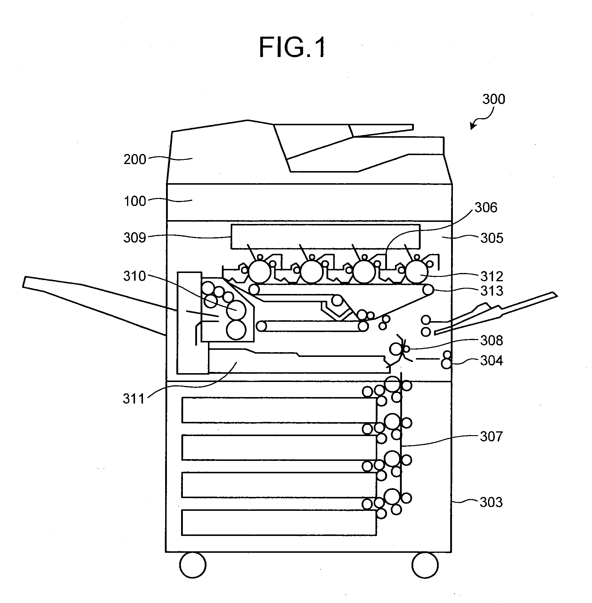
[0034]An image forming apparatus according to embodiments will be described below by referring to the accompanying drawings. FIG. 1 is a configuration diagram illustrating an exemplary structure of an image forming apparatus 300 according to an embodiment. The image forming apparatus 300 is configured as a digital copying machine and includes a paper feeder 303 and a body 304 of the image forming apparatus, with an image reading apparatus 100 and an automatic document feeder (ADF) 200 mounted thereon.

[0035]In the body 304 of the image forming apparatus, a tandem image forming unit 305, a resist roller 308 which transports recording papers supplied from the paper feeder 303 via a transport path 307 to the image forming unit 305, an optical writing device 309, a fixing and transporting unit 310, and a duplex tray 311 are provided.

[0036]In the image forming unit 305, four photoreceptor drums 312 are provided in parallel corresponding to four color toners of Y, M, C, and K colors. Image...


PUM


Abstract

An imaging device includes photoelectric conversion elements arranged unidirectionally for each color of light to be received, and performing photoelectric conversion of reflected light from an approximately same position of an object for the each color sequentially pixel by pixel; and a black correction unit that corrects a black level of the object with respect to a pixel group including some photoelectric conversion elements in a way that an output result of the photoelectric conversion of reflected light by a photoelectric conversion element for a pixel, independent of the reflected light, is subtracted from another output result of photoelectric conversion of reflected light by the photoelectric conversion element for the same pixel.

Description

CROSS-REFERENCE TO RELATED APPLICATION[0001]The present application claims priority to and incorporates by reference the entire contents of Japanese Patent Application No. 2013-211058 filed in Japan on Oct. 8, 2013.BACKGROUND OF THE INVENTION[0002]1. Field of the Invention[0003]The present invention relates to an imaging device, an image reading apparatus, an image forming apparatus, and image reading method.[0004]2. Description of the Related Art[0005]An image reading apparatus reads a document image by irradiating a document by a light source such as an LED, and converting the reflected light from the document to an image signal by an image sensor, and a CMOS image sensor, for example, has been known as one of such image reading apparatuses. There are factors to deteriorate the quality of the image read by the CMOS image sensor, and a known factor is fixed pattern noise that occurs due to variation of each pixel. When the fixed pattern noise is present, a resulting image after rea...

Claims


Application Information

Patent Timeline
Patent Type & Authority Applications(United States)
IPC IPC(8): H04N1/60
CPCH04N1/6002H04N1/4076H04N1/6008
Inventor MARUMOTO, KOHEINAKAZAWA, MASAMOTONAGASE, MASAKI
Owner RICOH KK
Why Eureka
Try Eureka