
Laser protective device with reflecting filter on non-absorbing and absorbing substrates

a technology of protective device and substrate, which is applied in the field of laser protective device with filter, can solve the problems of high-power lasers inflicting damage on eyes or devices, temporary or permanent blindness, and difficulty in seeing cockpit instruments or outside the cockpit, so as to reduce the impact, reduce vision, and reduce the effect of impa

Active Publication Date: 2015-04-02
IRIDIAN SPECTRAL TECH
View PDF7 Cites 9 Cited by
  • Summary
  • Abstract
  • Description
  • Claims
  • Application Information

AI Technical Summary

Benefits of technology

The patent text describes a technology that filters out harmful laser light from reaching the eyes or devices. The technology uses a partially transparent substrate that absorbs the laser wavelengths, reducing the intensity of light that may damage the eye. Additionally, the substrate can also provide good color discrimination. The technology is particularly useful in situations where there is a lot of light, such as wearing sunglasses with a reflecting filter to protect against UV light. Overall, the technology ensures that laser light is minimized while still providing protective eyewear.

Problems solved by technology

High power lasers can inflict damage to an eye or a device if the light from the laser is intentionally or accidentally directed to an unprotected eye or device.
These laser strikes can cause a significant glare hazard through dazzle which makes it very difficult to see cockpit instrumentation or see outside the cockpit.
Additionally, the laser might strike a pilot's eyes directly causing temporary or permanent blindness.
As another example, a person may be working with a high power laser that has the potential to cause significant eye damage if the laser light is accidentally directed to their eyes or others present in the same proximity to the high power laser.
As yet another example, a surveillance camera in a high security location may be accidently or intentionally disabled using a high power laser.
However, the disadvantage of these dyes is that they are not particularly wavelength selective.
Hence, absorbing lenses can undesirably block a significant portion of the visible spectrum resulting in a low luminance or photoptic transmittance through the lens.
As well, there can be a poor colour discrimination in these absorbing substrates which can prohibit their use.
In addition, the absorption material may break down after absorbing a high intensity of light; hence, the blocking may be substantially degraded and not provide the same laser blocking protection.

Method used


Image

  • Laser protective device with reflecting filter on non-absorbing and absorbing substrates
  • Laser protective device with reflecting filter on non-absorbing and absorbing substrates
  • Laser protective device with reflecting filter on non-absorbing and absorbing substrates

Examples


example

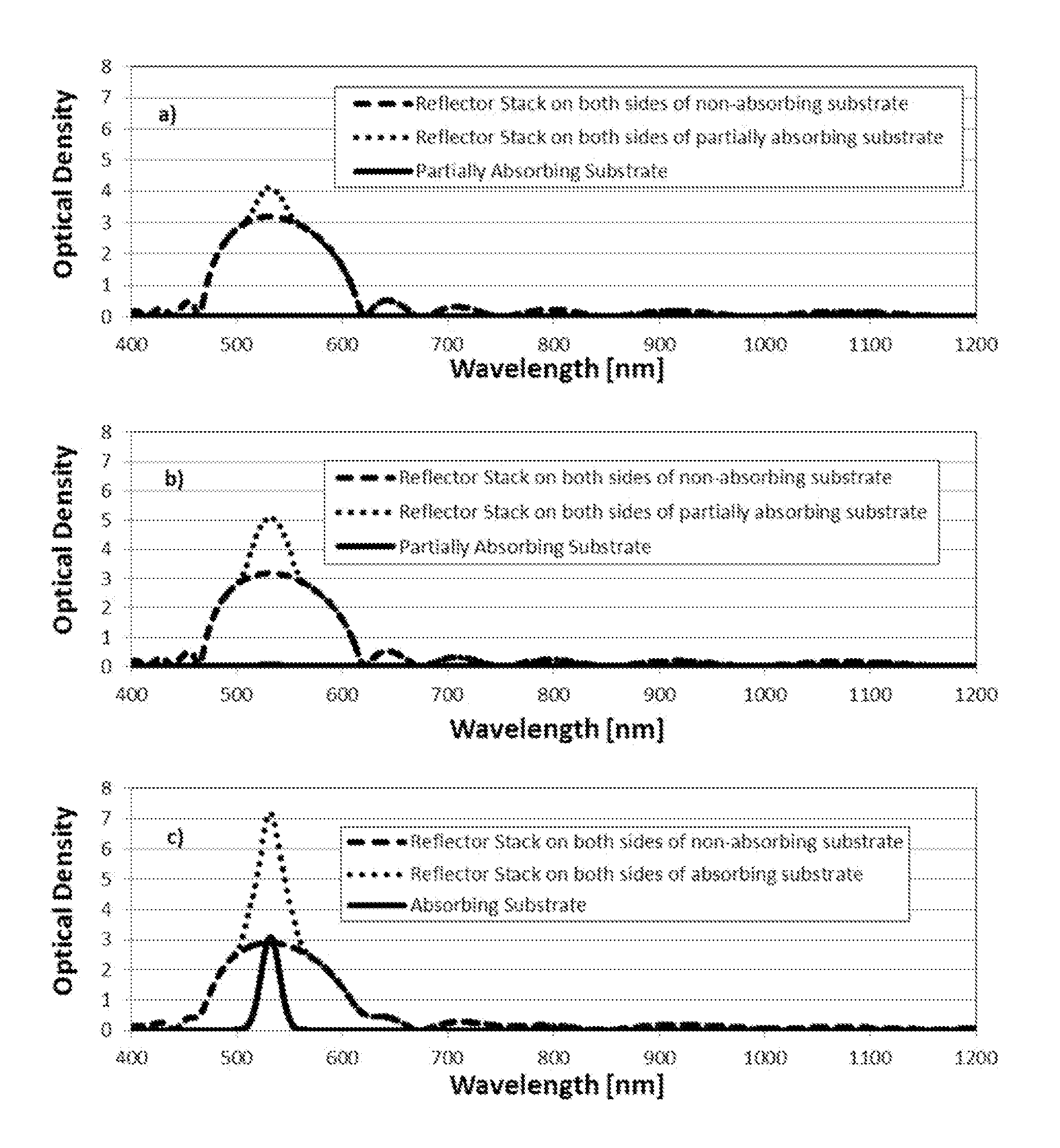
[0056]Three examples are provided that demonstrate some of the above embodiments using laser reflecting filters. In the examples provided, the laser reflector filters were designed using alternating layers of a low index material of SiO2 and a high index material of Nb2O5. A sputtering process was used to deposit the laser reflecting filters although other deposition methods could also be used. In addition, the deposition growth was optically monitored to determine that the desired layer thicknesses were deposited accurately; however, other monitoring methods could also be used (including depositing the laser reflecting filters based on time alone using known deposition rates).

[0057]In a first example, a non-absorbing plastic (polycarbonate) lens and fused silica glass flat substrates are coated on one side only with a laser reflecting filter designed to substantially reflect laser light centered at or around of 405 nm, 445 nm, 532 nm, 635 nm, 650 nm, 808 nm and 1064 nm. This laser ...


PUM


Abstract

A laser reflecting has a low transmittance at one or more laser wavelengths while substantially transmitting all other wavelengths in the spectral range of interest, is coated on one or both sides of an absorbing or non-absorbing substrate. A laser reflecting filter on both sides of an absorbing substrate can result in an enhancement of the absorption of laser light by multiple reflections of the laser light in the absorbing substrate. The high transmittance of the laser-reflecting filter at non-laser wavelengths results in a relatively high overall transmittance through the coated substrate. In the specific case of laser reflecting coatings on a lens to protect an eye, this allows a high luminous transmittance and good colour discrimination.

Description

CROSS REFERENCE TO RELATED APPLICATION[0001]This application claims the benefit under 35 USC 119 (e) of U.S. Provisional Application No. 61 / 885,116 filed Oct. 1, 2013 and Canadian Patent Application No. 2,828,687 filed Oct. 1, 2013, the contents of which are herein incorporated by reference.FIELD OF THE INVENTION[0002]This invention relates to the field of laser protective devices, and in particular to a protective device with filter for protecting the eyes or devices, such as surveillance cameras, from harmful laser light.BACKGROUND OF THE INVENTION[0003]High power lasers can inflict damage to an eye or a device if the light from the laser is intentionally or accidentally directed to an unprotected eye or device. As one example, airline and helicopter pilots have reported laser strikes where laser pointers are aimed at their cockpits. These laser strikes can cause a significant glare hazard through dazzle which makes it very difficult to see cockpit instrumentation or see outside t...

Claims


Application Information

Patent Timeline
IPC IPC(8): F21V7/00G02C7/10F21V9/06
CPCF21V7/0066G02C7/104F21V9/06G02B5/26G02B5/28
Inventor SULLIVAN, BRIAN THOMASCARLOW, GRAHAMOSBORNE, NORMAN RONALDBADEEN, ADAMPALIDWAR, JASON
Owner IRIDIAN SPECTRAL TECH
Learn More