
Method to stabilize ventricular rate during episodes of atrial fibrillation

a technology of atrial fibrillation and ventricular rate, which is applied in the field of atrial fibrillation stabilization and atrial fibrillation episodes, can solve the problems of patient discomfort, patient dizziness or fatigue, and ventricular fibrillation (vf) is an immediate life-threatening tachyarrhythmia, so as to avoid heart capture

Active Publication Date: 2015-03-26
PACESETTER INC
View PDF4 Cites 0 Cited by
  • Summary
  • Abstract
  • Description
  • Claims
  • Application Information

AI Technical Summary

Benefits of technology

The patent describes a technology that prevents the device from capturing the heart's natural electrical activity during stimulation. This means that the device can safely stimulate the nerves without causing any harm to the heart.

Problems solved by technology

However, ventricular fibrillation (VF) is an immediately life threatening tachyarrhythmia for which the device takes immediate and aggressive action.
The patient may experience dizziness or feel fatigued.
Although not immediately life threatening, it can also be unpleasant to a patient.
It results in rapid and chaotic activity of the atria of the heart.
The chaotic atrial activity in turn causes the ventricular activity to become rapid and chaotic.
Under these conditions, patients also experience dizziness or feel fatigued due to reduced cardiac output.
In addition to strokes, symptoms of atrial fibrillation may include fatigue, syncope, congestive heart failure, weakness and dizziness.
Unfortunately, many patients with chronic AF are resistant to such drugs.

Method used


Image

  • Method to stabilize ventricular rate during episodes of atrial fibrillation
  • Method to stabilize ventricular rate during episodes of atrial fibrillation
  • Method to stabilize ventricular rate during episodes of atrial fibrillation

Examples


first embodiment

[0058]In accordance with a first embodiment, the AV nodal refractoriness may be lengthened by delivering a series of pacing-like stimulation pulses during the AV node refractory period, thereby extending its interval. Preferably, the frequency of the AV nodal pacing is slightly higher than

1AVRP,

where AVRP is the AV nodal refractory period.

[0059]In another embodiment, continuous stimulation pulses (for neural stimulation) are delivered to stimulate the distal end of vagal nerves of the AV node. The bursts of stimulation pulses are preferably sub-threshold so that the heart is not captured by the pulses delivered near the AV node. The duty cycle of the bursts may be programmable to achieve the target ventricular rate.

[0060]To re-establish AV nodal conduction (turn the AV node back ON), the electrical stimulation of the node itself or the vagal innervations are temporarily stopped. The duration of this period is selected such that only one atrial activation passes through the AV node b...

second embodiment

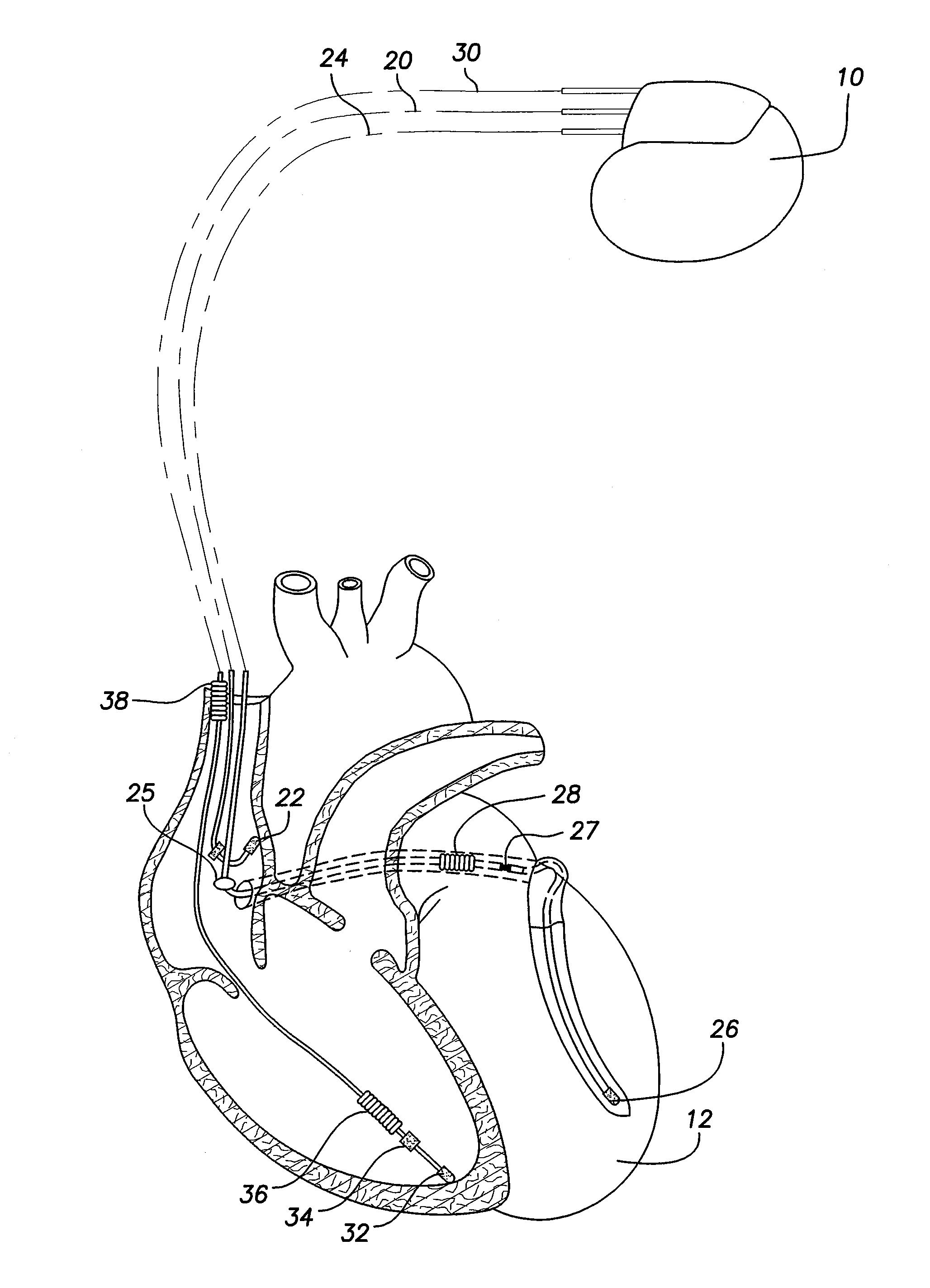
[0065]FIG. 4 shows a timing diagram illustrating a second embodiment to extend the AV nodal refractory period during episodes of AF to stabilize the ventricular rate. During T1, a plurality of stimulation pulses are delivered to stimulate the distal ends of vagal nerves in close proximity to the AV node. The opening period T2 is selected to pass only the first conduction from the atrium. The ventricular rate and stability is controlled by T1+T2. As previously mentioned, T1+T2 may be modulated by physiologic sensor 108. Preferably, the pulses have an energy and / or frequency that is sub-threshold and thus not capable of capturing the atria. The stimulation thus need not be delivered synchronously to a sensed atrial event.

[0066]In FIG. 5, a flow chart is shown describing an overview of the operation and novel features implemented in one embodiment of the device 10. In this flow chart, and the other flow chart of FIG. 6 described herein, the various algorithmic steps are summarized in i...


PUM


Abstract

A method to provide electrical stimulation therapy to stabilize ventricular rate of a heart during episodes of atrial fibrillation. The stimulation therapy may be a plurality of stimulation pulses delivered to the AV node during the AV node refractory period following the sensing of an atrial event.

Description

CROSS REFERENCE TO RELATED APPLICATIONS[0001]This application is a division of U.S. patent application Ser. No. 11 / 940,174, filed Nov. 14, 2007.FIELD OF THE INVENTION[0002]The present invention generally relates to an implantable cardiac stimulation device and method that provides electrical therapy to a patient's heart. The present invention more particularly relates to such a device and method that provides electrical stimulation therapy to stabilize ventricular rate of a heart during episodes of atrial fibrillation.BACKGROUND OF THE INVENTION[0003]Implantable cardiac devices are well known in the art. They may take the form of implantable defibrillators or cardioverters which treat accelerated rhythms of the heart such as fibrillation or implantable pacemakers which maintain the heart rate above a prescribed limit, such as, for example, to treat a bradycardia. Implantable cardiac devices are also known which incorporate both a pacemaker and a defibrillator.[0004]A pacemaker may b...

Claims


Application Information

Patent Timeline
Patent Type & Authority Applications(United States)
IPC IPC(8): A61N1/362A61N1/365
CPCA61N1/365A61N1/3624A61N1/368A61N1/3605A61N1/36053A61N1/395
Inventor PARK, EULJOONKIM, YOU-HOFARAZI, TARANEH GHAFFARI
Owner PACESETTER INC
Learn More