
Device for targeted guiding of a wheel relative to a vehicle body in case of a collision and adjusted wheel rim therefore

a technology for guiding wheels and vehicles, applied in vehicular safety arrangements, bumpers, pedestrian/occupant safety arrangements, etc., can solve the problems of entanglement of wheels, less effective or not effective as structures, and no longer effective conventional longitudinal members of vehicle bodies, so as to minimize the force required, the space requirement is very small, and the effect of space saving

Inactive Publication Date: 2015-03-26
AUDI AG
View PDF24 Cites 24 Cited by
  • Summary
  • Abstract
  • Description
  • Claims
  • Application Information

AI Technical Summary

Benefits of technology

The invention is a device that helps guide a wheel of a vehicle in case of a collision with another object. It has a capture device that attaches to the wheel and guides it in a way that it impacts the vehicle's body structure instead of the passenger compartment. This is important because it helps absorb the force of the collision and minimize damage to the vehicle. The capture device is designed as a thin plate that can bend softly about a vertical axis of the vehicle, making it space-saving and easy to install. It can hook with the tire or the wheel rim, depending on the circumstances. The first end of the capture device is usually fastened to a subframe or a console of the vehicle, which allows it to engage with the wheel in a simple and effective way.

Problems solved by technology

The development of offset crash tests shows a tendency toward including further load cases with small overlap, wherein for example an overlap of only 20% to 25%—defined according to the US American Institute for crash research IIHS as so called small overlap—measured from the obstacle-facing outside of the vehicle without mirror, results in the fact that the conventional longitudinal members of a vehicle body no longer directly participate in the collision and as a result are far less effective or not effective at all as structures for absorbing impact energy.
In particular there is the risk that in the event of a collision according to a small overlap scenario, a wheel becomes entangled with the obstacle and due to the enormous forces enters into the passenger compartment through softer regions of the vehicle body without being blocked by the longitudinal member structures before hand.
In a simulated collision with high impact energy as provided for by the US Institute for crash research IIHS this deflection device fails because in this case it unfavorably jams the wheel.
This causes the front wheel to be unfavorably clamped in the wheel case between the deflection device and the motor carrier so that the impact energy is compensated by less stiff vehicle body elements.
This may lead to unsafe deformations of the passenger compartment.
The deflection device includes a predetermined buckling site, which in case of a collision involving a small impact surface is bent and engages with its outer ends on the inner wheel rim flange of the front wheel and unfavorably jams the front wheel in the turned-in position in the wheel case so that the outer wheel surface forms an attack surface for further forces and / or torques.
For partially overlapping frontal collisions involving high impact energies however, the safety structure does not sufficiently protect the passenger compartment from deformations due to the insufficient stiffness.
Another disadvantage is also that in the case of a collision this deflection device causes the front wheel to be unfavorably turned in.
In the case of a collision with high impact energy, the scenarios of which are predetermined by the American Institute for crash research IIHS, the deflecting effect of the cantilever beam fails because the torsion resistant fixing of the cantilever beam is not stable enough so that the wheel in such collisions is then unfavorably displaced in the wheel case by the released cantilever beam.
The engagement mechanism engages on the outer wheel rim flange in the wheel so that depending on the circumstances the wheel is capable during the collision to be turned in outwardly with its front part which points in driving direction, thereby causing the risk that the turned-in wheel is pushed into the passenger compartment.

Method used


Image

  • Device for targeted guiding of a wheel relative to a vehicle body in case of a collision and adjusted wheel rim therefore
  • Device for targeted guiding of a wheel relative to a vehicle body in case of a collision and adjusted wheel rim therefore
  • Device for targeted guiding of a wheel relative to a vehicle body in case of a collision and adjusted wheel rim therefore

Examples


Embodiment Construction

[0044]Throughout all the Figures, same or corresponding elements are generally indicated by same reference numerals. These depicted embodiments are to be understood as illustrative of the invention and not as limiting in any way. It should also be understood that the drawings are not necessarily to scale and that the embodiments are sometimes illustrated by graphic symbols, phantom lines, diagrammatic representations and fragmentary views. In certain instances, details which are not necessary for an understanding of the present invention or which render other details difficult to perceive may have been omitted.

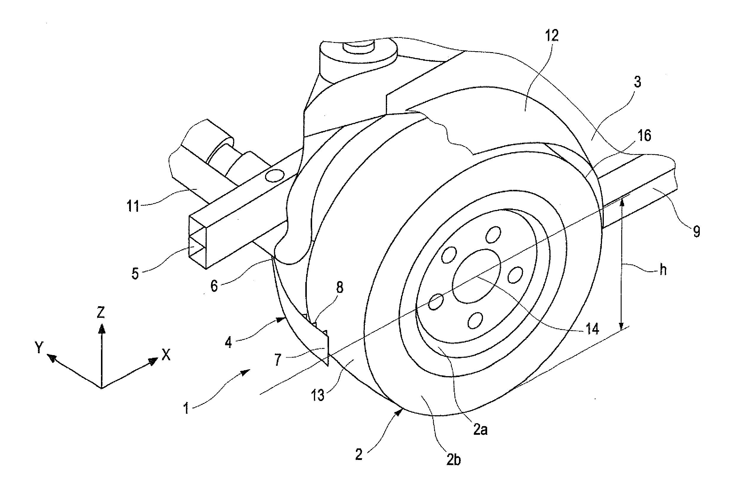
[0045]Turning now to the drawing, and in particular to FIG. 1, there is shown a device 1 according to the invention for targeted guiding of a wheel 2 relative to a vehicle body 3. The device 1 has a capture device 4 which has when viewed in a transverse direction Y of the vehicle a first end 6 arranged in the region of a longitudinal member 5 and a free second end 7. On the fr...


PUM


Abstract

A device for targeted guiding of a wheel relative to a vehicle body in the case of a collision includes a capture device for the wheel, which when viewed in the transverse direction vehicle is fastened on one end in the region of a longitudinal member of the motor vehicle and on its other free end is arranged with a distance before a wheel arranged in a wheel well, wherein the capture device in case of a collision engages the wheel and fixes and guides the wheel at least during the collision regarding its turning-in movement such that the wheel forms a part of a load path for introducing collision forces into a support structure of a passenger compartment.

Description

CROSS-REFERENCES TO RELATED APPLICATIONS[0001]This application claims the priority of German Patent Application, Serial No. 10 203 015 701.3, filed Sep. 20, 2013, pursuant to 35 U.S.C. 119(a)-(d), the disclosure of which is incorporated herein by reference.BACKGROUND OF THE INVENTION[0002]The invention relates to a device for targeted guiding of a wheel relative to a vehicle body in the event of a collision and an adjusted wheel rim therefore. In particular the device according to the invention is provided for the event of an impact of a vehicle with a obstacle with small vehicle overlap (small overlap crash) or with a small impact surface.[0003]The following discussion of related art is provided to assist the reader in understanding the advantages of the invention, and is not to be construed as an admission that this related art is prior art to this invention.[0004]For improving the safety in modern motor vehicles, automobile manufacturers expend great efforts to define increasingl...

Claims


Application Information

Patent Timeline
IPC IPC(8): B60R19/54B60B21/02B62D21/15
CPCB60R19/54B60B21/026B62D21/152B60B21/02B60R21/02B62D25/082B60R19/00B60R19/14B60R2019/007B60R2021/0023
Inventor KILLIAN, FRIEDRICHKRAMER, TOBIAS
Owner AUDI AG
Learn More