
Bumper structure and method for manufacturing bumper beam

a technology of bumper beams and beams, applied in the field of bumper beams, can solve the problems of low productivity and increased costs, and achieve the effect of improving collision energy absorption characteristics

Active Publication Date: 2015-03-12
KOBE STEEL LTD
View PDF4 Cites 9 Cited by
  • Summary
  • Abstract
  • Description
  • Claims
  • Application Information

AI Technical Summary

Benefits of technology

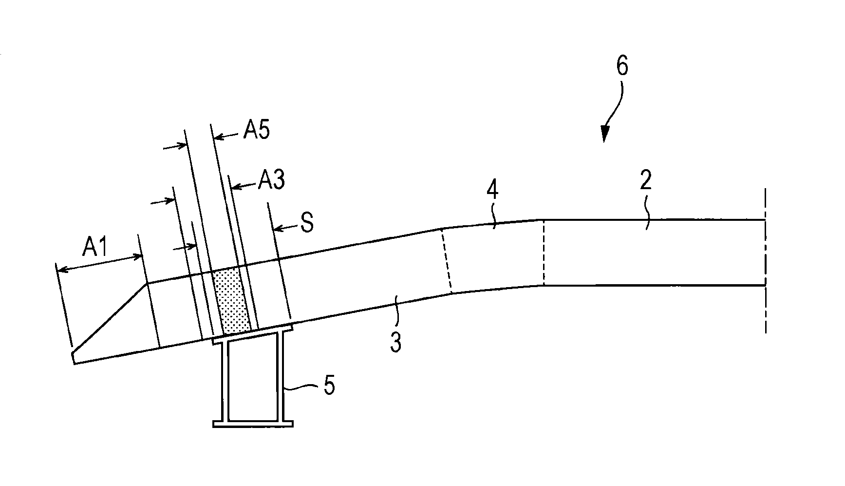
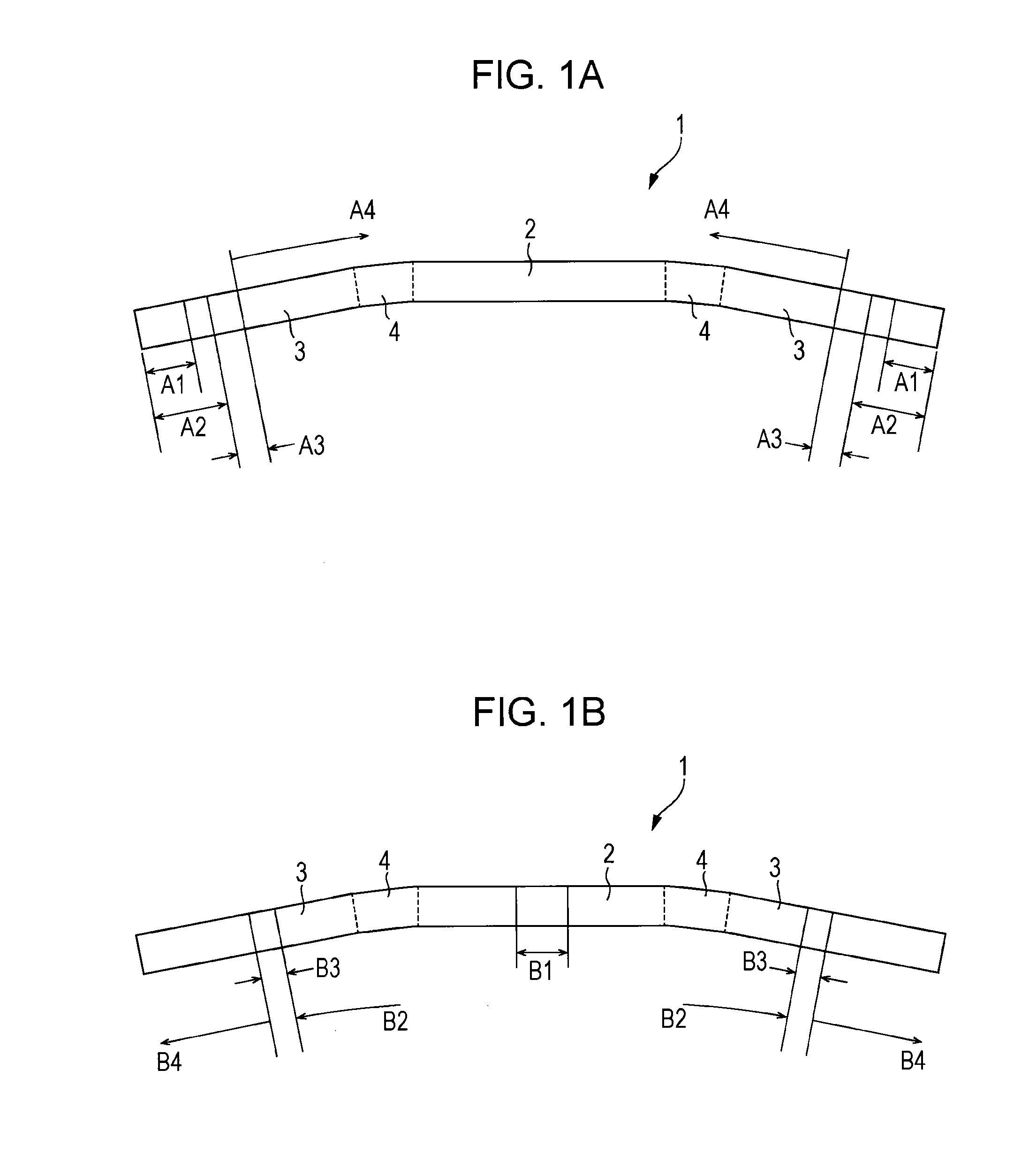
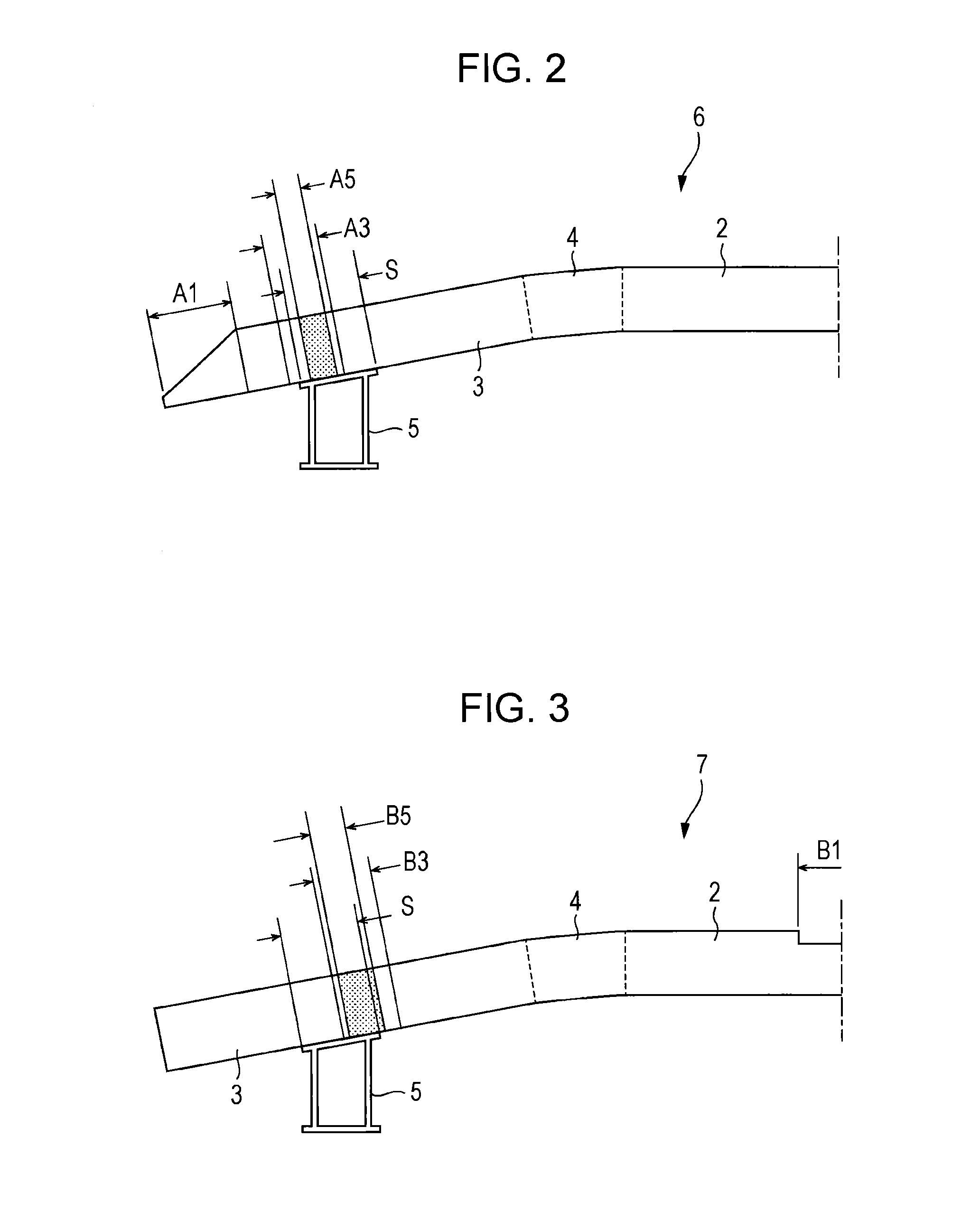
The present invention provides an efficient and cost-effective bumper beam that has a longitudinal portion subjected to plastic working, such as crushing, and a locally softened portion. The softened portion results from a heat treatment process that involves reversion treatment, age hardening, and annealing. The bumper beam has better collision energy absorption characteristics than bumper structures without the softened region. The invention also provides an inexpensive bumper structure that includes the bumper beam.

Problems solved by technology

The formation of a locally softened portion in a longitudinal portion (in particular, a joint for a bumper stay) of a bumper beam formed of a 6000 or 7000 series heat-treatable aluminum alloy extrusion subjected to plastic working, such as crushing, as described in Japanese Unexamined Patent Application Publication (Translation of PCT Application) No. 2010-502496, requires three heat treatments of reversion treatment, age hardening, and annealing, which are responsible for low productivity and increased costs.

Method used


Image

  • Bumper structure and method for manufacturing bumper beam
  • Bumper structure and method for manufacturing bumper beam
  • Bumper structure and method for manufacturing bumper beam

Examples


examples

[0052]A 7000 series aluminum alloy composed of Zn: 6.39 mass %, Mg: 1.34 mass %, Cu: 0.15 mass %, Fe: 0.11 mass %, Si: 0.04 mass %, Mn: 0.02 mass %, Cr: 0.03 mass %, Zr: 0.13 mass %, and Ti: 0.02 mass %, the remainder being aluminum and incidental impurities, was subjected to hot extrusion and was fan-cooled on a production line immediately after the extrusion (press quenching), thereby forming a hollow extrusion having a 60 mm×120 mm rectangular cross section. The hollow extrusion was cut into hollow extrusions each having a length of 1300 mm for 25 bumper beams.

[0053]Each of the hollow extrusions for bumper beams was subjected to natural aging at room temperature for 20 days (T1-tempered members) and was bent to form a bumper beam 11, as illustrated in FIG. 4. Twenty-five bumper reinforcing beams 11 were formed. The bumper beam 11 was bilaterally symmetric and included a central portion 12, an end portion 13, and a bent portion 14. With reference to left and right ends (zero point...


PUM

PropertyMeasurementUnit
temperatureaaaaaaaaaa
holding temperatureaaaaaaaaaa

Abstract

There is provided a bumper beam that is formed of a 7000 series aluminum alloy hollow extrusion, has a crushed longitudinal portion, and locally has a low-hardness region in a bumper stay joint section. A portion (portion to be heated) of end portions of the bumper beam formed of a tempered member of a heat-treatable aluminum alloy extrusion is subjected to reversion treatment, thereby forming a heat-affected zone in a bumper stay joint section. An end region (portion to be crushed) of the heated portion is subjected to cold crushing, and then the whole bumper beam is subjected to age hardening. The heated portion and a non-heat-affected zone are hardened through the age hardening, thereby forming a low-hardness region that overlaps the joint section in a portion of the heat-affected zone.

Description

BACKGROUND OF THE INVENTION[0001]1. Field of the Invention[0002]The present invention relates to a bumper beam formed of a heat-treatable aluminum alloy extrusion, a bumper structure including the bumper beam and a pair of bumper stays joined to both end portions of the bumper beam, and a method for manufacturing the bumper beam.[0003]2. Description of the Related Art[0004]Japanese Patent Nos. 3465862 and 4111651 and Japanese Unexamined Patent Application Publication Nos. 7-25296 and 2003-118367 disclose the manufacture of automotive reinforcing members, such as door beams and bumper beams, that includes crushing an end region of an aluminum alloy extrusion, which is composed of a pair of opposing flanges and a plurality of webs coupled to the flanges, in a direction perpendicular to a surface of the flanges. Japanese Patent No. 4111651 discloses crushing of a press-quenched 6000 series (Al—Mg—Si) aluminum alloy extrusion after age hardening. Japanese Unexamined Patent Application P...

Claims


Application Information

Patent Timeline
Patent Type & Authority Applications(United States)
IPC IPC(8): B60R19/18C22F1/053
CPCB60R19/18C22C21/10B60R2019/1826C22F1/053B60R2019/182
Inventor HASHIMOTO, NARIKAZUTSUYOSHI, TSUNETAKESHIKAMA, TAKAHIROKAJIWARA, HIROYUKI
Owner KOBE STEEL LTD
Learn More