
Multidimensional hydrodynamic focusing chamber

a hydrodynamic focusing and multi-dimensional technology, applied in the field of multi-dimensional hydrodynamic focusing chambers, can solve the problems of inability to accurately measure the hydrodynamic inability to adopt new methods, and inability to accurately measure the pressure of the focusing chamber

Active Publication Date: 2015-03-05
BIO RAD LAB INC
View PDF3 Cites 40 Cited by
  • Summary
  • Abstract
  • Description
  • Claims
  • Application Information

AI Technical Summary

Benefits of technology

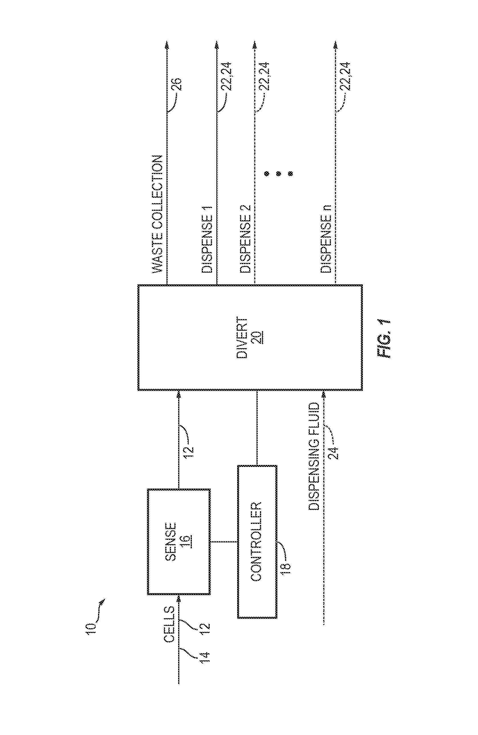
This patent describes systems and methods for manipulating, dispensing, and sorting particles like cells and beads using microfluidic technology. The systems include a shaped focusing chamber and a branched diverting mechanism. The technical effects of this invention include improved precision and accuracy in particle manipulation and sorting, which can be useful in various fields such as biological research and medical applications.

Problems solved by technology

Unfortunately, as the number of possible combinations of samples, reagents, and assays becomes nearly incalculable, it has become increasingly apparent that novel approaches are necessary even to begin to make sense of this complexity, especially within reasonable temporal and monetary limitations.
However, this method is not accurate: aliquots may contain no cell, one cell, or multiple cells.
However, pick-and-place systems need to locate each cell and require significant time if moving a substantial number of cells.
Single cells also may be analyzed using flow cytometry, but this method is complex and expensive, and not set up for or intended to dispense single cells.

Method used


Image

  • Multidimensional hydrodynamic focusing chamber
  • Multidimensional hydrodynamic focusing chamber
  • Multidimensional hydrodynamic focusing chamber

Examples


example 1

Dispensing System Having a Multi-Dimensional Hydrodynamic Focusing Mechanism

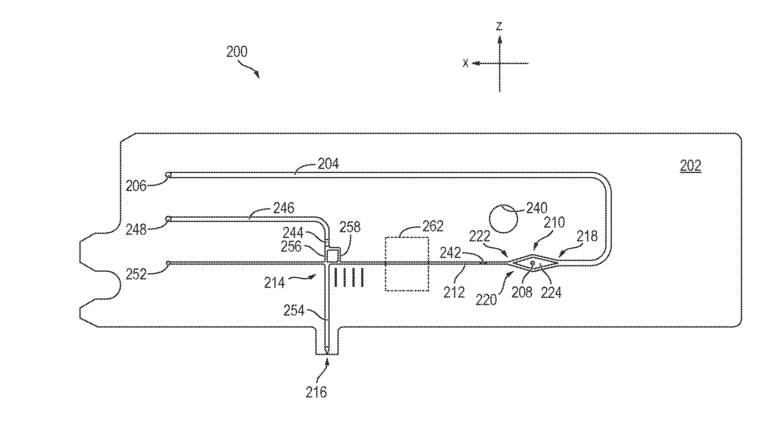
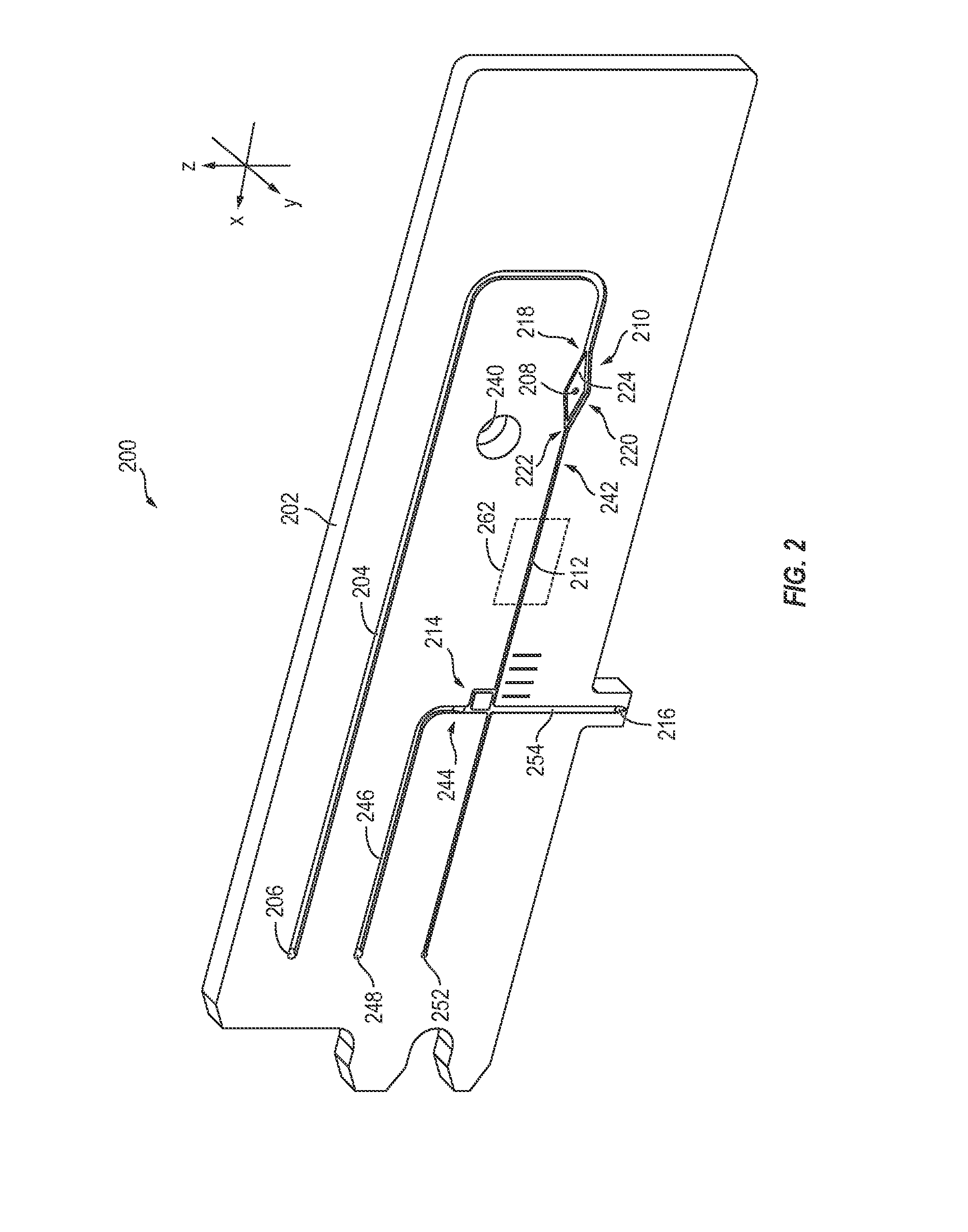
[0084]This example describes an on-demand cell dispensing system 200 having a hydrodynamic focusing mechanism according to aspects of the present disclosure; see FIGS. 2-11.

[0085]System 200 is an example of system 10 described above, embodied on a single layer microfluidics chip 202. System 200 includes a sheath fluid channel 204 having a sheath inlet port 206, a sample port 208, and a focusing mechanism 210 disposed at the intersection of sheath fluid channel 204 and the sample port. Sheath fluid and sample fluid combine in focusing mechanism 210, and exit the mechanism via a sheathed sample channel 212. System 200 may include a diverter mechanism 214, configured to divert particles of interest from channel 212 toward a dispensing nozzle 216.

[0086]In operation, chip 202 may be oriented as shown (i.e., on edge), with the dispensing nozzle pointed in a downward direction and the focusing mechanism oriented ve...

example 2

System

[0111]This example describes an on-demand cell dispensing system 700 according to the present disclosure; see FIG. 12.

[0112]FIG. 12 is a schematic diagram showing an illustrative system 700 which is an example of system 10. System 700 includes a microfluidics chip 702 on which is located a system including the channels, focusing mechanism, and one or more diverter mechanisms described above. Chip 702 may include one or more attachment and / or reference points for facilitating assembly and alignment, such as apertures, recesses, and the like. Various devices such as valves, sliders, vacuum chambers, and other components that may be located on chip 702, or on other equipment operatively connected thereto, are caused to operate by actuators 704 such as solenoid valves. These actuators 704 are in turn activated by switches 706 controlled through an input / output (I / O) system 708 by a processor 710. Processor 710 may include a microprocessor, such as the processor of a typical person...

example 3

Selected Embodiments

[0114]This section describes additional aspects and features of on-demand particle dispensing systems, presented without limitation as a series of paragraphs, some or all of which may be alphanumerically designated for clarity and efficiency. Each of these paragraphs can be combined with one or more other paragraphs, and / or with disclosure from elsewhere in this application, including the materials incorporated by reference in the Cross-References, in any suitable manner. Some of the paragraphs below expressly refer to and further limit other paragraphs, providing without limitation examples of some of the suitable combinations. References to preceding paragraphs, such as “paragraph A” or “any of the preceding paragraphs,” are to paragraphs within the same subsection of “selected embodiments.”


PUM

PropertyMeasurementUnit
volumesaaaaaaaaaa
volumesaaaaaaaaaa
volumesaaaaaaaaaa

Abstract

Systems, including apparatus and methods, for the microfluidic manipulation, dispensing, and / or sorting of particles, such as cells and / or beads. The systems may include a shaped focusing chamber and / or a branched diverting mechanism.

Description

CROSS-REFERENCES[0001]This application is based upon and claims the benefit under 35 U.S.C. §119(e) of the following U.S. provisional patent applications: Ser. No. 61 / 874,320, filed Sep. 5, 2013; and Ser. No. 61 / 902,664, filed Nov. 11, 2013. Each of these applications is incorporated herein by reference in its entirety for all purposes.INTRODUCTION[0002]The ability to perform molecular and cellular analyses of biological systems has grown explosively over the past several decades. In particular, the advent and refinement of molecular and cellular techniques, such as DNA sequencing, gene cloning, monoclonal antibody production, cell transfection, amplification techniques (such as PCR), and transgenic animal formation, have fueled this explosive growth. These techniques have spawned an overwhelming number of identified genes, encoded proteins, engineered cell types, and assays for studying these genes, proteins, and cell types. Unfortunately, as the number of possible combinations of ...

Claims


Application Information

Patent Timeline
Patent Type & Authority Applications(United States)
IPC IPC(8): B01L3/00G01N15/14
CPCB01L3/502776G01N15/1404B01L3/502761B01L2200/0636G01N2015/1413B01L2300/0819B01L2300/0848B01L2200/0652B01L2300/0864B01L3/0265B01L2200/027B01L2200/0689B01L2200/12B01L2200/146B01L2200/147B01L2200/16B01L2300/021B01L2300/044B01L2300/0636B01L2300/0816B01L2300/088B01L2300/165B01L2300/18B01L2400/0409B01L2400/0415B01L2400/0457B01L2400/0688B01L2400/082B01L2400/084B01L2400/0644B01L2400/065B01L2400/0655Y10T436/25Y10T436/25375G01N15/149C12Q1/24G01N15/1459
Inventor SADRI, AMIR M.ROSENZWEIG, TALKIRCANSKI, NENAD
Owner BIO RAD LAB INC
Learn More