
Two-fluid hydrodynamic printing

a hydrodynamic printing and hydrodynamic printing technology, applied in the field of additive manufacturing, can solve the problems of excess energy input to the ink, limiting the use of this technology for commercial applications, and limiting the usefulness of conformal printing

Active Publication Date: 2018-11-20
NAT TECH & ENG SOLUTIONS OF SANDIA LLC
View PDF3 Cites 1 Cited by
  • Summary
  • Abstract
  • Description
  • Claims
  • Application Information

AI Technical Summary

Benefits of technology

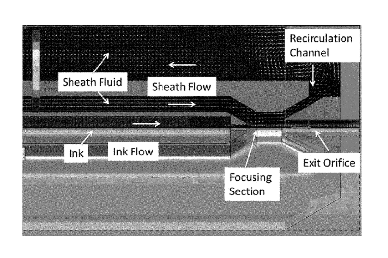
The patent describes a new technology for printing electronics and other high-performance applications using a special print head. This technology allows for the separation and reuse of excess fluid, and printing results showed the removal of more than 81% of the excess fluid without affecting the print stream. The printed features were approximately 2 μm in diameter, suggesting the print head had a cross-section of approximately 2 μm. This technology also allows for the printing of insulated conductors and clad optical interconnects.

Problems solved by technology

Although the AJ technology has been demonstrated in a laboratory environment, several technical issues persist that limit the use of this technology for commercial applications.
These issues include:1. Shuttering—The mechanical shutter used for AJ printing limits its usefulness for conformal printing and has a tendency to eject excess ink collected in the shutter during printing onto the print surface.
As such, excess energy input to the ink changes ink characteristics over time and affects the output of the printer.
This requires tight temperature control and makes this system more complex.4. Aerosol Transport—The physical sizes of the UAs and PAs necessitate mounting the atomizer some distance from the print head.
These pressure pulses affect the print quality.5. Multiplexing Print Nozzles—AJ has had some success developing multinozzle print heads but, in addition to the above issues, individual nozzle shuttering and uniform aerosol distribution present additional challenges in scaling the AJ technology.6. Material Output Rate—Aerosol theory shows that diffusion limits the number of droplets that can exist within a given space at any given time and that the number of droplets that can exist is independent of droplet size for the droplet range of interest to AJ printing.
This limits the maximum output rate for AJ technology using current UA and PA technology.

Method used


Image

  • Two-fluid hydrodynamic printing
  • Two-fluid hydrodynamic printing
  • Two-fluid hydrodynamic printing

Examples


Embodiment Construction

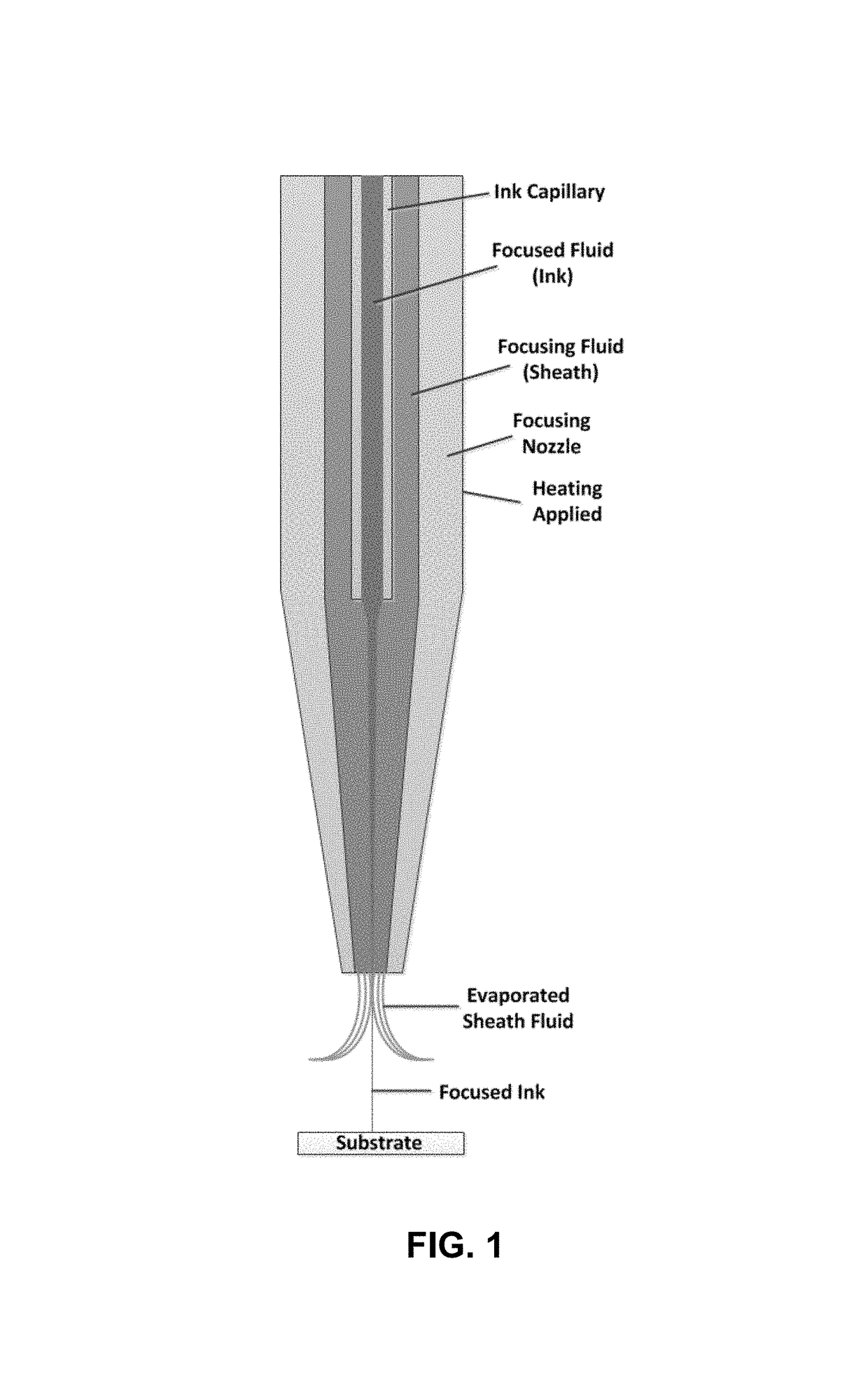
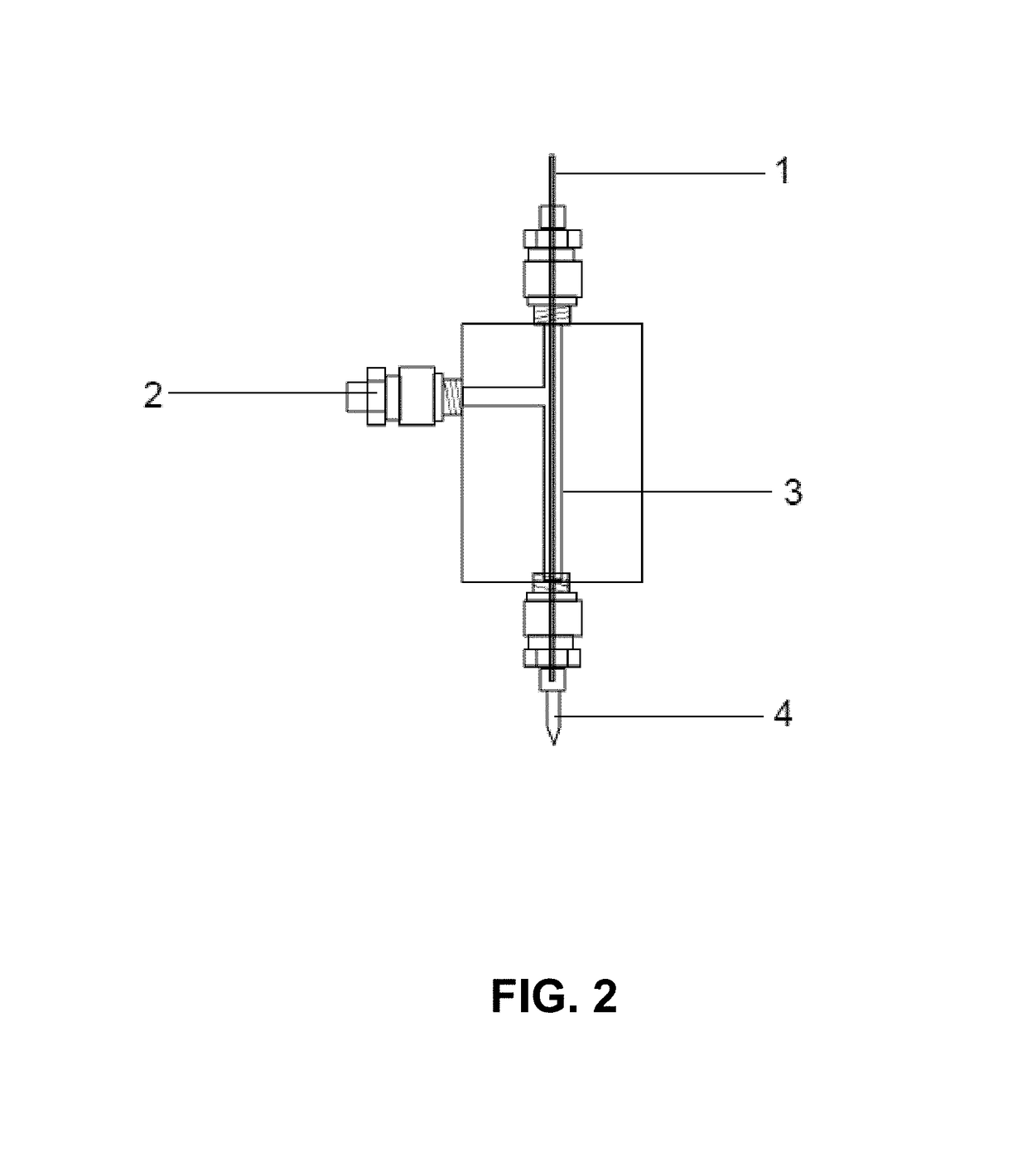
[0023]Many of the existing issues associated with AJ technology can be overcome with the use of a liquid jet printing method using hydrodynamic focusing. Hydrodynamic focusing of fluids occurs in microchannels when multiple fluids flow into the same channel and the flow rate of a focusing fluid is increased with respect to a focused core fluid. If the two fluids differ enough in their velocity (or density), they do not mix and form a two-layer stable flow. This effect is illustrated in FIG. 1, which shows hydrodynamic focusing in a coaxial tube assembly. Focused fluid (ink) is introduced into the coaxial tube via a central ink capillary. The focused fluid is injected at the end of the capillary into the middle of a sheath flow of a focusing fluid. Increasing the flow rate of the focusing fluid decreases the cross-sectional area of the core ink fluid causing focusing. The focusing effect can be further enhanced by flowing the two fluid streams through a converging focusing nozzle. Up...


PUM

PropertyMeasurementUnit
diameteraaaaaaaaaa
diameteraaaaaaaaaa
diameteraaaaaaaaaa

Abstract

Hydrodynamic focusing of two fluid steams provides a novel micro printing technology for printed electronics and other high performance applications.

Description

CROSS-REFERENCE TO RELATED APPLICATION[0001]This application claims the benefit of U.S. Provisional Application No. 62 / 076,776, filed Nov. 7, 2014, which is incorporated herein by reference.STATEMENT OF GOVERNMENT INTEREST[0002]This invention was made with Government support under contract no. DE-AC04-94AL85000 awarded by the U.S. Department of Energy to Sandia Corporation. The Government has certain rights in the invention.FIELD OF THE INVENTION[0003]The present invention relates to additive manufacturing and, in particular, to a method and apparatus for two-fluid hydrodynamic printing of electronic features.BACKGROUND OF THE INVENTION[0004]Printed electronics is an emerging area for additive manufacturing used to create electrical devices on various substrates. The appeal to directly print electronic features is driven largely by the advantages offered to reduce process steps, capital equipment costs and the need for product specific tooling. By addressing these points, Direct Wri...

Claims


Application Information

Patent Timeline
Patent Type & Authority Patents(United States)
IPC IPC(8): B29C64/209B29C64/245B29C64/20B05B7/06B29C67/00B33Y30/00B29C64/112B29C64/357
CPCB05B7/06B05B7/066B29C64/112B29C64/20B29C64/245B29C64/357B33Y30/00B29C64/209B29K2039/06
Inventor KEICHER, DAVID M.COOK, ADAM
Owner NAT TECH & ENG SOLUTIONS OF SANDIA LLC
Learn More